README.md
# Rev C update

The latest design adds a fourth 50 x 48 mm board with an isolated AC/DC converter. **Read POWER-REV-C.md first**; it supersedes Rev B's external adapter requirement and specifies the 600 mA output limit. All four boards remain engineering prototypes pending mains integration review and hardware tests.

# Switch Rev B — directly populated, three-board prototype

Rev B replaces the module-carrier design. Each PCB is 50 x 48 mm and uses two copper layers with tscircuit local autorouting. The previous carrier and trial designs are archived outside this package in ../switch-pcb-development-history.

| Board | Source | Directly populated components |
|---|---|---|
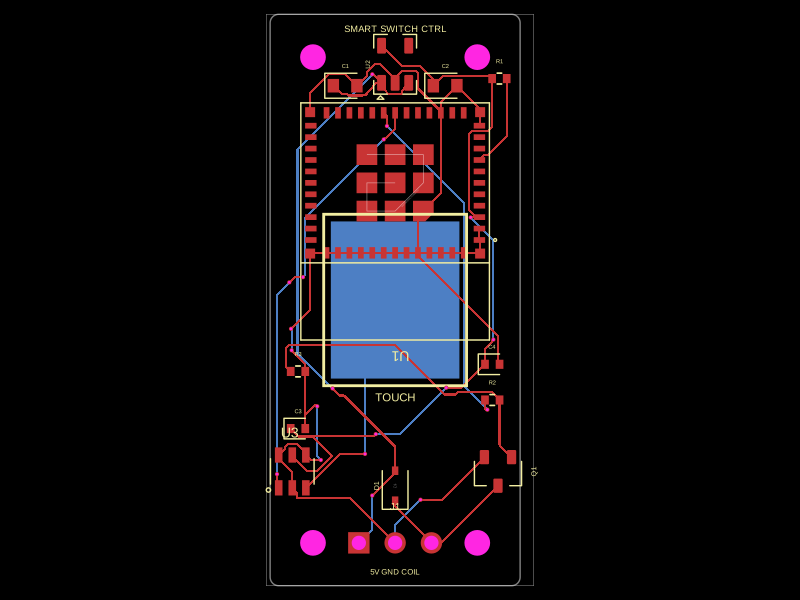
| ESP controller | index.circuit.tsx | Ai-Thinker ESP-12F castellated ESP8266 module, AP2112K-3.3 regulator, boot resistors, supply capacitors |
| Touch panel | touch.circuit.tsx | TTP223-BA6 IC, 16 x 16 mm PCB copper electrode, local supply capacitors |
| Relay | relay.circuit.tsx | G5Q relay itself, AO3400A coil driver, gate resistors, flyback diode |

ESP-12F is soldered directly to this PCB. There is no NodeMCU/D1-mini development board socket. The touch sensor and relay are actual components, not external module placeholders. Headers are used only for inter-board wires, power and programming.

## Power and interconnections

Use an external certified, isolated regulated 5 V supply rated at least 1 A. The three PCBs do not convert 230 V AC into 5 V. Neutral is available per the user, but selecting and installing the isolated supply is an enclosure/integration task. Never connect line or neutral to the 5 V or touch headers.

Controller J1: pin 1 +5 V, pin 2 GND, pin 3 unused (3-pin imported header). Controller J3 -> relay J1: 1 +5 V, 2 GND, 3 GPIO12/D6 relay command. Controller J4 -> touch J1: 1 +3.3 V, 2 GND, 3 GPIO13/D7 touch output. Match pin numbers, not cable appearance. Touch is direct active LOW (AHLB=3.3 V, TOG=GND), matching the previously observed firmware polarity. Relay is active HIGH and has gate pulldown for a default OFF state.

Controller J2 programming: 1 GND, 2 ESP TXD (programmer RX), 3 ESP RXD (programmer TX), 4 GPIO0/BOOT, 5 RST. Use 3.3 V UART logic only, power the controller from J1, pull BOOT low while resetting to flash, release BOOT for normal startup. Disconnect all mains before programming or probing. No firmware has been flashed by this task. Existing GPIO12/13 HTTP-control firmware can be adapted to ESP-12F; it is not delivered preprogrammed. ESP-12F has no NodeMCU onboard indicator LED or USB programmer.

## Relay and appliance selection

The drawn default part is G5Q-1A4-EL3-HA DC5, selected for a fan/motor application. Its 5 V coil uses about 80 mA, hence the transistor and flyback diode. For capacitive LED lighting, select the G5Q-1A4-EL2-HA variant after checking the lamp's inrush and exact availability/coil variant. Do not substitute the generic G5Q-EU and assume the same motor/inrush performance. Manufacturer reference: https://omronfs.omron.com/en_US/ecb/products/pdf/en-g5q_el.pdf

The relay footprint is now imported directly from JLCPCB C1519216 and agrees with the verified KiCad G5Q-1A pad coordinates (pins 1/5 coil, 2 COM, 3 NO), with a courtyard envelope that accommodates the EL family. Mechanical fit must still be checked against the ordered part. Source: https://github.com/KiCad/kicad-footprints/blob/master/Relay_THT.pretty/Relay_SPST_Omron-G5Q-1A.kicad_mod

Relay J2 is the imported KF301-5.0-2P screw terminal: pin 1 LINE input, pin 2 switched LINE output. Secure and strain-relieve conductors in the enclosure. Neutral and protective earth bypass the relay contacts and retain their appropriate appliance connections. Single-pole ON/OFF only, not fan-speed control, a service isolator or an approved two-way switch replacement.

A 6 mm wide copper exclusion band separates the PCB logic/contact regions; the relay footprint itself straddles the band. This is a layout measure, not a safety certification. The relay's own insulation, copper clearances, wire terminations, fusing, material, enclosure and installation must be reviewed together.

User confirmed one light OR one fan and neutral in the box, but has not provided appliance nameplate current/watts or inrush. India does not imply one appliance current rating. No complete-board mains current rating is assigned. The relay component's datasheet rating is not the PCB/system rating. Fuse selection, motor/LED switching life, surge suppression, insulation testing and enclosure temperature tests remain required before wall installation. Do not manufacture/install this as an approved wall switch based only on the software checks.

## PCB / assembly notes

Four 3.2 mm mounting holes on each board, centres (+/-21, +/-20) mm. Verify enclosure and screw clearances before assembly; keep metal fixings and inter-board wiring out of mains isolation and antenna regions. Keep the touch panel physically away from relay contacts/mains wiring, behind a nonconductive cover; solder mask alone is not a user-touch safety barrier. Sensitivity must be tuned with the actual cover and wire length. No ground copper is placed beneath the electrode.

C1/C2/C4 on controller: 10 uF X5R/X7R, 0805, select capacitance after DC-bias derating; C3: 100 nF. AP2112 input/output capacitors must meet its datasheet requirements. Touch C1=100 nF, C2=4.7 uF. All are nonpolarized ceramic capacitors. Driver diode D1: 1N4148W in SOD123, cathode to +5 V. ESP EN/RST/GPIO0/GPIO2 have 10 kohm pullups; GPIO15 has a 10 kohm pulldown. Relay control has 100 kohm pulldowns. Controller supply input has no reverse-polarity protection. AP2112 power dissipation at 5-to-3.3 V needs thermal verification under sustained Wi-Fi load in the final enclosed stack; its 600 mA current specification is not permission to dissipate arbitrary power.

## Build / inspect

    bun node_modules/tscircuit/cli.mjs build index.circuit.tsx --pcb-png --schematic-png --autorouter-debug
    bun node_modules/tscircuit/cli.mjs build touch.circuit.tsx --pcb-png --schematic-png
    bun node_modules/tscircuit/cli.mjs build relay.circuit.tsx --pcb-png --schematic-png
    bun node_modules/tscircuit/cli.mjs dev --port 3021

Use the local preview file picker for each circuit. Rendered/routed outputs are in dist/index, dist/touch and dist/relay. BUGS.md records tooling findings; logs preserve validation evidence locally. No production Gerber release, hardware assembly, live mains testing or electrical certification has occurred.

Primary references: https://documentation.espressif.com/esp8266_hardware_design_guidelines_en.html ; https://www.diodes.com/datasheet/download/AP2112.pdf ; https://www.tontek.com.tw/uploads/product/243/TTP223-BA6_V2.1_EN.pdf . Imported JLCPCB/LCSC geometry is pinned in imports/ and must be cross-checked against the purchased component revision.

## JLCPCB-only assembled parts

All assembled parts in the three Rev B circuits are imported components from JLCPCB with exact EasyEDA footprints in imports/. See JLCPCB-BOM.csv for references, quantities and part numbers. The 3-pin power header has its third pin unused. Electrode E1 is PCB copper and do-not-place; mounting holes, keepouts, traces and text are fabrication features, not purchased parts. Catalog IDs do not guarantee current stock or compatibility with a selected JLC assembly service. No order has been placed.

The relay default is the motor-rated C1519216 for the requested one-fan option; an LED load still needs its inrush checked before choosing the relay variant. The full board has no certified mains rating.


## Verified revision status

All three final routed outputs have zero circuit error records. Netlist, schematic placement and PCB placement checks pass; final PCB placement has zero warnings. Gerber-derived checks report no shorts for each board. These checks establish software connectivity/layout validation only. All boards are two-layer, 50 x 48 mm. Controller explicitly uses tscircuit beta_pipeline1 at 5x effort: it completed 36 routes with zero router errors. Pipeline9 failed on the same controller; see BUGS.md and debug/. Touch/relay use the default local tscircuit pipeline. No production safety approval is implied.

Imported connector footprints have added insertion-direction metadata (vertical headers from_above; KF301 wire entry from_y_neg before the board rotation). Pad geometry remains the exact imported geometry.