hrithik18k/switch-pcb
A tscircuit package created by hrithik18k.
- Version
- 1.2.0
- License
- unset
- Stars
- 0
POWER-REV-C.md
# Rev C — board-mounted isolated mains power

Rev C adds power.circuit.tsx as a FOURTH 50 x 48 mm, two-layer PCB. The controller, touch and relay boards remain 50 x 48 mm. The AC/DC converter is a directly soldered Mean Well IRM-03-5, JLCPCB C6969425. This replaces the external adapter in the architecture; no discrete transformer/mains converter was invented.

## Connections and limits

Power J1 pin1 = LINE, pin2 = NEUTRAL. LINE passes through F1, Littelfuse 0215001.MXEP T1A 250 VAC time-delay ceramic fuse, C178837, before the converter input. Its manufacturer's 215-series breaking capacity is 1500 A at 250 VAC; installation prospective fault current and backup protection must be assessed. This fuse protects the converter branch ONLY, not the appliance branch. Never route fan/bulb load current through the power PCB. Fuse suitability for startup inrush and protection coordination must be tested.

Power J2 pin1 = isolated +5 V, pin2 = isolated return/GND, pin3 unused. It supplies controller J1 pin1/+5 V and pin2/GND; the controller then distributes power to the single relay and touch board through their existing interconnections. Do not connect another adapter or programmer power output simultaneously. The module supplies 5 V up to 600 mA total, NOT 1 A. This supersedes the older external-supply current recommendation in README.md. Reserve 80 mA for the relay coil, about 500 mA peak allowance for ESP supply design and small additional logic current; peak margin is tight. This is a one-relay prototype, no extra loads. Measure voltage dips during Wi-Fi transmit and relay operation, and test enclosed temperature/derating. If 600 mA is insufficient, use a larger converter and revise the layout; do not uprate by changing a label or fuse.

Mains LINE also feeds relay board LINE terminal through separately suitable load protection; relay output feeds the one selected appliance. Appliance neutral is separate from isolated GND. Protective earth remains continuous where required. OFF does not isolate the power board: it remains energized. This is not a maintenance isolator, speed controller, socket/heater switch, or finished certified wall-switch product.

## Isolation and mechanical design

The PSU is nominally 37 x 24 x 15 mm. Additional space is needed for the PCB, solder joints, wiring bend radius, standoffs and enclosure. Four board mounting holes at (+/-21,+/-21) mm; check mechanical stack because the other boards use +/-20 mm y centres. Do not blindly stack the touch panel above mains circuitry. Keep mains wires away from low-voltage boards, touch electrode, antenna, programming access and metal hardware. The enclosure must prevent access to both faces of the live power/relay PCBs and provide appropriate insulation/fire containment and strain relief. Solder mask is not an insulation barrier.

Power PCB has an 8 mm horizontal copper-exclusion band across BOTH layers, centred y=6 mm, with only the isolated converter body exempted. Do not put copper pours/traces across it. The imported converter footprint includes NC pin13, which remains unconnected, and mechanical holes; verify every feature against the ordered module and its manufacturer's mounting drawing. Do not insert metal screws into the module footprint holes by assumption.

No optional MOV is fitted: an ordinary MOV requires coordinated thermal/fault protection and surge validation. The converter is used within its documented application scope; external surge protection, EMC and appliance transient suppression must be reviewed and tested for the actual installation. A module's own approvals do not certify the PCB, wiring, stack or complete wall switch. Complete-product standards, load current/inrush, dielectric withstand, leakage, insulation/creepage, fuse coordination, abnormal operation, surge/EMC and temperature remain release gates. Board-level DRC is not a mains compliance test.

## JLCPCB parts added

| Ref | Part | JLCPCB |
|---|---|---|
| PS1 | Mean Well IRM-03-5 | C6969425 |
| F1 | Littelfuse 0215001.MXEP | C178837 |
| J1 | KF301-5.0-2P | C474881 |
| J2 | 2.54 mm 1x3 header | C49257 |

All are imported with exact EasyEDA geometry. Catalog/import availability is not a guarantee of stock or factory assembly availability. Output inspection should include verifying terminal orientation, fuse lead spacing and module pin map. No order or hardware mains energization has occurred.

Primary references:
- https://www.meanwell.com/Upload/PDF/IRM-03/IRM-03-SPEC.PDF
- https://www.littelfuse.com/assetdocs/littelfuse_fuse_215_datasheet.pdf?assetguid=990f7193-d9a2-48e4-b760-2b43514249cf
- https://jlcpcb.com/partdetail/IRM-03-5/C6969425
- https://jlcpcb.com/partdetail/Littelfuse-0215001MXEP/C178837

Build: bun node_modules/tscircuit/cli.mjs build power.circuit.tsx --pcb-png --schematic-png --autorouter-debug
Short check: bun node_modules/tscircuit/cli.mjs check shorts dist/power/circuit.json

The mains terminal is on the right-hand lower edge, rotated to make its actual wire entry accessible. Extra imports not instantiated by the circuits are not BOM parts. Never use the converter branch fuse as appliance-load protection.


Final Rev C power-board software validation: netlist passed (0 errors/warnings), schematic placement passed, PCB placement reports no placement issues (0 errors/warnings), routed build passed with 5 copper traces and zero circuit error records. The 8 mm exclusion band is present on top and bottom in the generated autorouter input. Gerber copper-short result is recorded in power-shorts-vc.log. Previous failed layout checks were corrected, not waived. None of these software results constitutes installation or product safety certification.
Related Packages
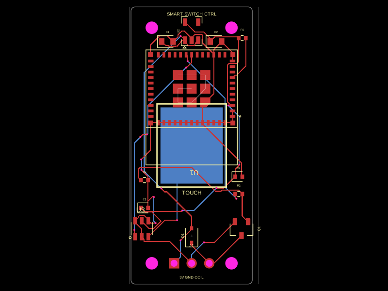 More from this authorhrithik18k/smart-switch-pcbThe AO3400A component models a SOT-23 N-channel MOSFET with labeled pins for Gate, Source, and Drain, including 3D CAD models and schematic symbols for electronic circuit design.
 Discover something newDevesh36/pocket-audio-playerA portable, rechargeable microSD audio player built around an RP2040, SPI flash, USB‑C charging/power management, LCD/button controls, PCM5102A I²S DAC, and TPA6132A headphone amplifier in a 3D‑printed enclosure.