README.md
# Lamp Clip — 60 mm head PCB, Rev B

Editable tscircuit engineering design for a book-mounted reading light with camera, microphone, Wi-Fi and spoken responses. **Prototype under review; not a manufacturing release.** This package is hardware source, not tested hardware or finished Muse firmware.

## Open and edit

Install Node.js and Bun, then in this directory. Install the local dependencies before starting dev: otherwise the global CLI can fall back to a different bundled browser runtime:

```sh
bun install --frozen-lockfile
bun run dev
```

The entry point is `index.circuit.tsx`. For this version of the PCB viewer, right-click the board and choose **Rendering Engine → Canvas**; the experimental WebGPU renderer cannot display through-pad traces. Dependencies are pinned to the tool version used here. Components with nonstandard footprints are defined in the adjacent TSX files; imported land patterns are stored locally in `imports/`. All thirteen IC/module definitions (U1–U13), Q1 and D1 use local JLCSearch/EasyEDA imports. `component-provenance.csv` records the exact supplier IDs, import paths and documented corrections. The build does not depend on a live component search service.

```sh
bun run typecheck
bun run check:netlist
bun run check:schematic
bun run check:placement
bun run placement
bun run build
bun run check:shorts
```

`placement` compiles without routing. `build` replays the saved, corrected route through normal tscircuit validation and writes `dist/index/circuit.json`, PCB and schematic PNGs. The saved route is guarded against any changed geometry or netlist. To change placement or wiring, run `bun run reroute`, inspect and correct its results, then recapture the routing source as described in `routing-notes.txt`. Fresh autorouting can take several minutes. Inspect all output and the process exit status; a render can exist even if a check fails. Do not confuse a successful image export with an electrically valid design.

## What is in the head

| Function | Selected implementation |
|---|---|
| Main board | 60 mm circular, 4 layers, 1.6 mm; top = rear electronics, bottom = page side |
| Wi-Fi / processor | ESP32-S3-WROOM-1U-N16R8, 16 MB flash / 8 MB PSRAM; separate antenna required |
| Camera | KLT KLT-PAA40-OV5640-1B V1.0 ESP32, 24-contact direct FPC with autofocus |
| Microphone | INMP441 digital I2S, bottom acoustic port; obsolete R7 prototype selection |
| Audio output | MAX98357A amplifier in the head; 8-ohm speaker in the clip base |
| Reading light | Six warm-white XL-3216WWC LEDs, constant-current series string, nominal 15 mA |
| Charging | USB-C 5 V, BQ24074 power path and remote cell temperature sensing |
| Logic power | TPS63021 3.3 V buck-boost |
| Controls | Ask, light and hardware on/charge-only switch; USB programming/recovery pads |

This has one custom main PCB plus the purchased sensor/lens assembly on flex. J2 is a Hirose FH12-24S-0.5SH(55), imported from JLCSearch C202112 with its 3D model. Camera rails and level conversion now live on the main board: U8/U9 supply 2.8 V and 1.5 V; U10–U13 handle signal levels. See `camera-sourcing.txt` for the direct supplier and exact variant.

## What stays in the clip base

A protected 1S Li-ion/LiPo cell, a cell-mounted 10k Semitec 103AT-2 thermistor, and the physical speaker. Six conductors pass through the gooseneck:

| J3 pin | Connection |
|---|---|
| 1 | Battery positive |
| 2 | Battery negative / ground |
| 3 | Cell thermistor |
| 4 | Thermistor return / ground |
| 5 | Speaker positive, amplifier output |
| 6 | Speaker negative, amplifier output |

**Speaker negative is not ground.** Keep the speaker pair together and physically separated from the microphone wiring/acoustic path. Use strain relief and wire gauges suitable for measured peak battery current. The gooseneck must not be used as the electrical return.

## Mechanical assumptions

The KLT drawing specifies a 21.25 mm flex assembly and an 8.5 × 8.5 × 5.07 mm lens block. The page-side FPC faces inward to keep the ribbon inside the head. Allow latch/tool access and a nonconductive lens support. The 9 mm silkscreen box is a provisional alignment guide; confirm a physical sample before defining the aperture. Only the connector has a supplied 3D model. The optical assembly and its support need mechanical CAD.

Four nominal 2.2 mm mounting holes are provided. USB-C and the charge-only switch face the left edge. The microphone sound opening needs an unobstructed acoustic channel. The selected ESP32 module needs a suitable external 2.4 GHz antenna; antenna placement and RF performance must be tested in the plastic enclosure. The gooseneck attachment, spring clip and optical/privacy-shutter mechanics are not included as CAD.

## Muse integration boundary

Use the [Muse Gadget SDK](https://github.com/facebookincubator/muse-gadget-sdk) as the firmware starting point. Its ESP32 foundation, voice recording and camera backend are relevant, but this board needs a custom hardware definition, camera driver/configuration, I2S mapping and power policy. The proposed interaction is press Ask, capture the page, record the question, obtain the assistant response and play audio.

Do not assume the current voice-message path automatically includes a photo or returns synthesized speech. Image/voice association and text-to-speech playback still require implementation and end-to-end testing. See `firmware-and-assembly.txt` and `pin-map.csv` for the actual wiring and integration work.

## Before an assembled prototype

- Finish the routing and manufacturability review documented in `validation.txt`; verify USB pair geometry, camera clock/data timing, converter current loops and thermal returns against manufacturer layouts.
- Select exact passive part numbers, including capacitance after DC bias. SW1/SW2 use E-Switch TL3305AF160QG with audited manufacturer lands and contact pairs; confirm assembly orientation and enclosure actuator fit. The imported INMP441ACEZ-R7 is an obsolete prototype selection and must be replaced/qualified before a production design.
- Review all custom land patterns, the bottom FPC orientation and latch access, microphone acoustic pad and exposed-pad paste/thermal-via treatment with the assembler. The intentional thermal vias in exposed pads require a filled/capped via-in-pad process (or a reviewed redesign). `isViaInPadAllowed` declares that manufacturing choice; copper clearance and short checks remain enabled.
- Complete the USB power policy. This board defaults to **100 mA** and permits 500 mA only after host enumeration. An ordinary wall adapter remains at 100 mA, so charging a 2000 mAh cell takes well over 20 hours. A production product needs appropriate charger/current detection for faster standalone charging.
- Replace or qualify the prototype VBUS presence detector for valid voltage thresholds and detach timing; test suspend behavior in all power states, including charge-only mode.
- Test power rails first from a current-limited supply, then programming, camera, microphone, speaker and light independently. Test cell temperature cutoff, low-battery handling, charging, thermal rise and fault recovery before enclosure trials.

No battery-life, reading-distance, audio-quality or manufacturing-cost measurement is claimed. A useful next physical milestone is one electrically reviewed engineering assembly with its exact camera, battery, antenna and speaker, followed by firmware bring-up.

## Files

- `index.circuit.tsx`: main board and net connections.
- `*-parts.tsx`, `usb-connector.tsx`, `imports/`: audited/corrected component definitions.
- `schematic-layout.tsx`: nine annotated functional schematic sheets; preserves PCB coordinates.
- `bill-of-materials.csv`: procurement list with selected, generic and pending parts explicitly marked.
- `component-provenance.csv`: JLCSearch references and exact footprint adaptations.
- `pin-map.csv`: physical module pad / GPIO / net mapping.
- `firmware-and-assembly.txt`: camera setup, harness, firmware boundary and bring-up.
- `power-audit.txt`, `usb-power-policy.txt`: detailed design review and known limits.
- `validation.txt`: final tool results and release status.
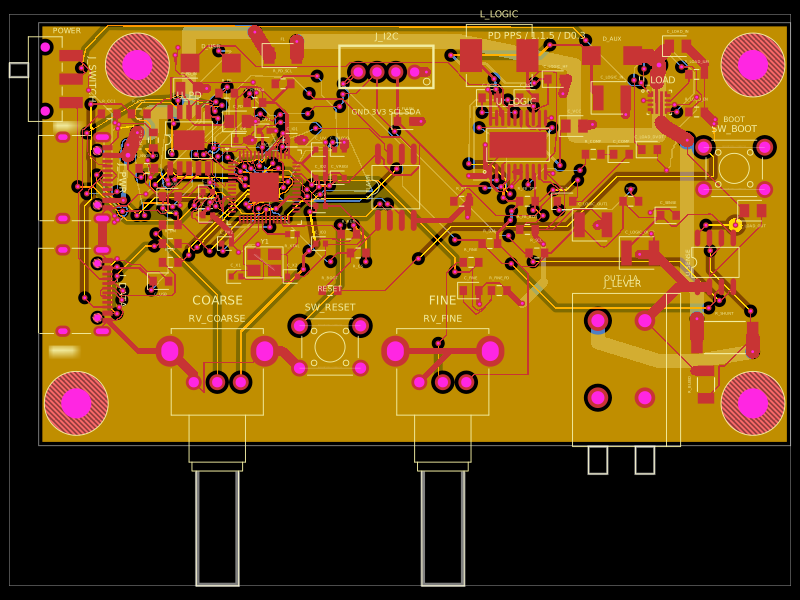
- `preview.html`: local design review page, with board views and a selector for all nine schematic sheets.
- `schematic-sheets/`: one SVG and PNG per numbered sheet.
- `schematic.svg`: all nine sheets stacked into a single overview.

Primary component documentation is linked in the source files, BOM and audit. Earlier development-module guides are not the wiring instructions for this custom PCB.

## Direct camera revision (0.2.0)

Nine annotated schematic sheets cover USB-C, charging and harness, 3.3 V, MCU, camera signals, camera power, audio, reading light, and controls. J1 continues to use `<connector standard="usb_c" />`. The ESP32 GPIO assignment is preserved; PCB copper is freshly routed for the new camera interface.

Order the exact camera in `camera-sourcing.txt` and use `camera-pinout.csv` to inspect every FPC contact. Kai Lap publishes a direct sales contact; sample stock, price, MOQ and page-distance autofocus performance require supplier confirmation. The camera pinout is variant-specific: pin23 is NC and pin24 is 2.8 V AF power. This revision replaces the Adafruit #5840 + 18-pin header interface.

## Via size update (0.2.1)

All vias use a 0.30 mm hole and 0.45 mm outer copper diameter. Both board minimums and explicit/saved-route via sizes are updated. Routing follows the existing checked paths; the revised copper is rebuilt and checked for shorts on all four layers.

## Cloud build entrypoints (0.2.4)

`includeBoardFiles` explicitly selects `index.circuit.tsx`. The cloud builds and validates the saved, reviewed routing. `reroute.circuit.tsx` is an opt-in engineering tool invoked by `bun run reroute`; it is not part of normal CI. The worker timeout remains 20 minutes. See `cloud-build-investigation.txt` for measured timings and the v0.2.3 failure diagnosis.

## Indicator polarity fix (0.2.5)

LED7 is XINGLIGHT XL-1608SYGC-06 (JLC C965805, yellow-green) and LED8 is XL-1608UOC-06 (C965800, orange). Both use pin 1 cathode and pin 2 anode, explicit JLCSearch imports and CAD models. The orange import’s pad numbering is corrected against the manufacturer drawing to agree with its cathode mark. Both are placed at 180 degrees. Four trace endpoints were updated to the selected footprints and all four layers checked for shorts. Normal builds now keep supplier checks enabled; `bun run check:release` independently rejects circuit error records and audits both LED polarities.