muse/book-reading-clip-lamp
A 60‑mm ESP32‑S3 lamp-head PCB combining USB‑C battery charging/power regulation, OV5640 autofocus camera interfacing, I²S microphone and differential speaker audio, six‑LED boost-driven reading light, buttons, status indicators, and battery monitoring.
- Version
- 0.2.5
- License
- unset
- Stars
- 0
firmware-and-assembly.txt
Schematic

LAMP CLIP HEAD — REV B FIRMWARE AND ASSEMBLY NOTES
05 October 2026

These notes apply to the custom PCB sources in this folder. Earlier wiring
instructions for separate development modules are not this board's netlist.
This is an engineering prototype design; no assembled hardware, measured battery
life, completed enclosure or working lamp firmware is supplied.

WHAT GOES WHERE
Head: 60 mm main PCB, ESP32-S3-WROOM-1U-N16R8, separate Wi-Fi antenna,
camera assembly, microphone, speaker amplifier, reading LEDs, USB-C, charger,
regulators and controls. The radio has 16 MB flash and 8 MB octal PSRAM.
Base: protected rechargeable battery, cell-mounted thermistor and speaker.
The camera is a replaceable autofocus sensor/lens on flex, plugged into J2.
There is one custom main PCB, with camera regulators and buffers on that PCB. Digital camera/audio signals stay inside the head.

CAMERA - DIRECT FLEX CONNECTION
Use KLT-PAA40-OV5640-1B V1.0 ESP32 from Kai Lap Technologies. Fit Hirose
FH12-24S-0.5SH(55) at J2 on the page-facing bottom side. This replaces the
Adafruit daughterboard and 18-pin header used in Rev A.

Read camera-sourcing.txt and camera-pinout.csv before ordering or inserting
anything. J2 is keyed to the exact KLT drawing, not a generic OV5640 pinout.
Supplies: AVDD/DOVDD/AFVDD=2.8 V; DVDD=1.5 V. Contact23 is NC, contact24 is AFVDD.
U8/U9 generate rails; U10/U11 buffer camera outputs to 3.3 V; U12 translates
MCU control outputs to 2.8 V; U13 translates SCCB. Do not feed 3.3 V directly
into the ribbon. CAM_PWDN defaults high and CAM_RESET/XCLK default low.

Insert and remove the ribbon only with power off. Check polarity by pin number,
close the latch evenly, and retain the lens mechanically without pulling on its
flex. The camera drawing quotes a 21.25 mm flex assembly and an 8.5 x 8.5 x 5.07 mm
lens block; confirm physical samples before freezing the bezel or mounting.
The PCB lens box is only an alignment suggestion. J2 intentionally faces inward
for internal assembly, so an edge-accessibility warning is retained in DRC.

Before firmware capture, verify rail sequencing and external XCLK against the
camera datasheet. Use the esp32-camera OV5640 driver with PSRAM/JPEG and correct
autofocus initialization. No onboard oscillator/VM solder jumper is present.
See camera-sourcing.txt for the supplier and detailed bring-up sequence.

SIX-WIRE GOOSENECK HARNESS
The J3 order below follows the PCB pin numbers, not a generic cable standard.

J3 pin   Head net       Base connection
1        VBAT          Protected battery pack positive
2        GND           Protected battery pack negative
3        NTC           Cell-mounted thermistor lead 1
4        GND           Dedicated thermistor return lead 2
5        SPK_P         Speaker positive
6        SPK_N         Speaker negative

Start with high-flex 22–24 AWG battery wires and suitably flexible smaller
signal/speaker wires, then verify neck bore, temperature rise and voltage drop
with the real harness. Twist the speaker pair; insulate both neck exits and
provide strain relief outside the moving section. Keep the thermistor return
separate through the neck. Check insulation to the metal neck while bending it.

Both speaker wires are driven outputs of the MAX98357A. Neither goes to GND,
battery negative or the metal neck. Begin with an 8-ohm speaker rated at least
1 W and a firmware volume limit. Qualify speaker wiring/filtering for class-D
EMI using the actual neck; a short bench speaker lead is not representative.

BATTERY, TEMPERATURE AND USB POWER
Starting pack target: protected 1-cell Li-ion/LiPo, 3.7 V nominal / 4.2 V charge,
around 2000 mAh, vendor-approved for at least 0.6 A charging and 2 A continuous
discharge. Capacity is a packaging target, not a battery-life promise.
Use a cell-mounted Semitec 103AT-2 10k thermistor (B25/85=3435 K) or qualify
an electrically equivalent curve. Do not substitute a fixed resistor for the
thermistor in an assembled rechargeable product.

With this curve, the BQ24074's nominal 28k/4k temperature thresholds correspond
to roughly -0.6/+51 degrees C. Match or adjust the sensing network to the
selected pack's allowed charge temperatures; a pack limited to 45 degrees C
needs a tighter cutoff. Validate open/short sensor faults and real temperatures.

USB input defaults to 100 mA. GPIO21 selects 500 mA only after the USB host has
configured the device and permits it. Reset the selection on disconnect and
reset/deconfiguration. VBUS presence alone does not authorize 500 mA.
GPIO3 now drives the charger's EN2 through net USB_SUSPEND, retaining its
10k boot pulldown. It is a strapping pin at reset and a control output after
the strap is latched; preserve the intended reset state and eFuse policy.
Charger EN2/EN1 states: 00=100 mA, 01=500 mA, 10=ILIM (about 957 mA),
11=input suspend. To enter suspend, set EN1/GPIO21 high before EN2/GPIO3 high.
To resume, lower EN2 first, then set EN1 according to the current policy.
Never pass through state 10 accidentally. Retain both GPIO levels during
sleep, and validate all transitions on the real USB host.
This board has no CC-current/BC1.2 detector:
a plain wall supply remains in the default mode without another validated
current-authorization mechanism. Battery power may supplement active loads.

SW3 disables the 3.3 V regulator for charge-only recovery of a depleted pack.
It is not a battery isolation switch: the charger and SYS-fed amplifier/LED
driver remain physically connected, with control pulldowns keeping them off.
With the processor unpowered, EN1/EN2 return to 00 (100 mA). Charge-only mode
therefore does not retain USB suspend. Whole-device suspend-current and
off-state behavior remain unverified; do not claim USB compliance yet.
GPIO43's revised VBUS detector is active-low; use USB for development logs.

Power source: https://www.ti.com/lit/ds/symlink/bq24074.pdf
Thermistor: https://www.semitec-global.com/products/thermistor_at/
Amplifier: https://www.analog.com/media/en/technical-documentation/data-sheets/max98357a-max98357b.pdf

FIRMWARE — MUSE IS AN INTEGRATION TASK
SDK inspected at commit 693cde9a884ad1edc87251b9f8944815f8de4809.
The ESP32 SDK supports ESP32-S3, pairing/Wi-Fi and push-to-talk voice notes.
Its camera abstraction accepts a board-supplied JPEG capture/release backend;
the Watcher implementation demonstrates JPEG/base64 capture. This custom
OV5640 board still needs its own board definition, DVP camera backend and
registration of the capture capability. Page-image delivery associated with
the correct question must be tested against the actual Muse account.

The upstream gadget replies are TEXT. Add a text-to-speech service at the
documented start_tts integration point and play its audio through the I2S
amplifier to deliver the requested spoken answers. Do not advertise this
PCB as providing Muse voice replies merely by flashing the stock SDK.
The SDK currently specifies ESP-IDF 6.0.1 and an SDK token for pairing.
Commercial service access/terms must be established before selling units.

Implementation order:
1. Add a no-display board definition with 16 MB flash, octal PSRAM, USB,
   buttons and the pin map in index.circuit.tsx. Bring up 3.3 V first.
2. Add espressif/esp32-camera, JPEG capture in PSRAM and OV5640 autofocus.
   Start with one frame buffer. Its optional AF helper loads sensor firmware;
   trigger focus and wait for completion before taking the page image.
3. Configure standard I2S: GPIO4=BCLK, 5=WS, 6=amp data, 7=mic data.
   Use 64 BCLK per stereo frame; the left-slot INMP441 provides 24-bit samples.
   Convert to the SDK's 16 kHz PCM16 voice input and format playback correctly.
4. Implement half-duplex Ask behavior: mute speaker, record while held, capture
   and timestamp the page, complete the question turn, then synthesize/play
   the reply. Handle stale images, cancellation, retries and memory limits.
5. Keep GPIO8 amplifier enable and GPIO9 light control low during startup.
   Test lamp brightness/exposure together to avoid glare and PWM banding.
   GPIO44 Ask is not an RTC deep-sleep wake input; GPIO2 Light can wake it.
6. Implement safe USB-current state changes, battery ADC calibration, low
   battery handling and privacy controls. Prove reconnect and interrupted
   playback on hardware. Do not include production credentials in source.

Sources:
https://github.com/facebookincubator/muse-gadget-sdk/blob/693cde9a884ad1edc87251b9f8944815f8de4809/esp32/README.md
https://github.com/facebookincubator/muse-gadget-sdk/blob/693cde9a884ad1edc87251b9f8944815f8de4809/esp32/components/camera/camera.h
https://github.com/facebookincubator/muse-gadget-sdk/blob/693cde9a884ad1edc87251b9f8944815f8de4809/esp32/components/muse/boards/watcher_camera.c
https://github.com/facebookincubator/muse-gadget-sdk/blob/693cde9a884ad1edc87251b9f8944815f8de4809/esp32/components/muse/muse_chat_session.cpp
https://github.com/espressif/esp32-camera

ASSEMBLY AND BRING-UP
Use professional SMT assembly for the QFNs and bottom-port microphone. Review
the mic's segmented solder-paste ring before ordering; keep solder, adhesive
and enclosure material out of its acoustic hole. Fit the radio antenna behind
plastic, clear of the gooseneck and copper, following Espressif antenna rules.

Inspect/clean the assembled board, check rail-to-ground resistance, and verify
the harness polarity before connecting a battery. Bring up on a current-limited
supply with camera/speaker disconnected, then add camera, low-volume audio and
LEDs in stages. Measure charging and rail transients, focus/page legibility,
microphone intelligibility, Wi-Fi range and closed-enclosure temperatures.
Measure operating and sleep current before quoting battery life.

The imported INMP441ACEZ-R7 ordering option is obsolete. Qualify a microphone
intended for new designs before volume production; another MEMS microphone is not
automatically pin/footprint compatible.
https://product.tdk.com/en/search/sw_piezo/mic/mems-mic/info?part_no=INMP441

SW1/SW2 assembly detail:
Use E-Switch TL3305AF160QG normally-open tactile switches. The body is
4.5 x 4.5 mm and actuator height is 3.8 mm. In controls-parts.tsx, logical
pin1 joins physical pins1+2 (lower row), and logical pin2 joins physical
pins3+4 (upper row). The official land pattern and contact pairs were reviewed;
assembler review should confirm orientation and enclosure actuator fit.
Apply firmware debounce appropriate to the physical button.
Source: https://www.e-switch.com/wp-content/uploads/2023/01/TL3305.pdf
Related Packages
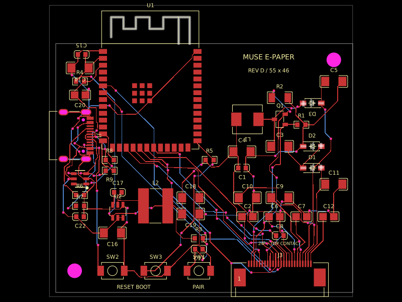 More from this authormuse/esp32-eink-displayA 55×46 mm two-layer ESP32-S3 e-paper controller board with USB‑C power/programming, buck regulation, FPC display connector, UC8179-style boost/charge-pump circuitry, ESD protection, controls, and routed passive components.
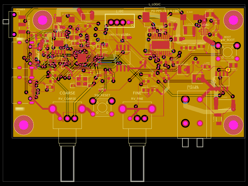 Discover something newastra/pd-power-supplyUSB-PD Power Supply with RP2040 controller