muse/book-reading-clip-lamp
A tscircuit package created by muse.
- Version
- 0.4.6
- License
- unset
- Stars
- 0
base-parts-and-assembly.txt
LAMP CLIP BASE — M12 — 3 NOVEMBER 2026

The enclosure, lid, lower clip jaw, speaker cradle, terminal shelf, spring guide
and TPU grip pads remain printable. The battery, speaker, buttons, terminals,
spring and hinge fasteners are real catalog parts. No bottom PCB is required.
Shopping links: base-shopping-list.csv. Source dimensions: base-catalog-parts.json.
These instructions supersede M10/M11 cable preparation and the bare thermistor.

PRINTED PACKAGING
Case: 64 x 92 x 42 mm (hinge and controls protrude beyond this case envelope).
Panel: 2 mm thick, two 16.2 mm holes for the stock 16 mm buttons.
Battery reserve: manufacturer maximum 38.5 x 62 x 8.5 mm, including protection
circuit. Store headline dimensions are smaller; do not size the case from them.
Battery-to-terminal-shelf gap: 1.95 mm before any adhesive/strain relief.
Speaker: retained ordered CES-30207-158L120-67; max 30.5 x 20.2 x 7.2 mm.
Thermistor: stock prewired 103AT-11; max protected body 15 x6.2 x5 mm, at SIDE of cell. Add electrical
insulation with good thermal coupling; never leave bare joints against pouch.
Hinge: ream printed holes 4.3 mm; M4 x70 bolt, two M4 washers and locking nut.
Printed 4.75 OD /4.3 ID guide centers the catalog spring around the hinge bolt.

PURCHASED PARTS
1 Adafruit 2011 protected 1S 2000 mAh battery (MECHANICAL CANDIDATE ONLY).
1 Adafruit 3814 PH2 male-to-bare-wire 200 mm pigtail; preserve battery plug.
1 Adafruit 1445 momentary Chat button.
1 Adafruit 1442 latching OFF/charge button. Unused LED tabs capped separately.
1 pack Adafruit 1152 quick-connect pairs; only two pairs required.
5 WAGO 222-412 two-wire, ONE-potential blocks.
1 WAGO 222-415 five-wire, ONE-potential ground block.
1 Molex 2181130204 425 mm PicoBlade cable; keep male 51047 speaker end.
Already ordered: Same Sky speaker and raw Semitec 103AT-2.
For the pictured minimum-soldering assembly, source a stock prewired 103AT-11
instead of making an extension for the raw 103AT-2. No purchases have been made.
1 WB Jones TMR-0304-035 spring candidate (force/travel not qualified).
1 Accu SSC-M4-70-A2 bolt, 2 HPW-M4-A2-BL washers, 1 HNN-M4-A2 nut.
4 Accu SSCF-M2-6-A2 lid screws; 2 SSCF-M2-4-A2 speaker-cradle screws.
See CSV for exact sources and stock/qualification cautions. No purchases made.

WHAT STILL NEEDS PREPARATION
The two buttons accept stock 1152 push-on sockets. No solder on the buttons.
Cut off the unneeded JST ends of 1152 leads, trim, and strip 9–10 mm for WAGO.
Keep the protected battery plug and its full nominal 100 mm red/black leads.
Use stock 3814 to mate it. Its free ends are already bare; trim to the trial
assembly length and strip 9–10 mm for WAGO. This replaces adapting a 500 mm
extension; no battery connector crimping or soldering is needed. Work unplugged.
The modeled thermistor is now factory-prewired Semitec 103AT-11: 10k ohm 1%,
B3435 1%, matching the former nominal electrical curve. Trim/split/strip its
600 mm insulated parallel leads directly into the two NTC WAGO blocks. There
are NO custom thermistor solder joints in this configuration. Confirm thermal
mounting/response; this change does NOT correct the 45 C charging-cutoff hold.
Your already-owned raw 103AT-2 is still an alternative for bench work, but it
requires a prepared insulated extension and is not the minimum-soldering model.
The long 28 AWG Molex speaker cable can run through the neck: remove its FEMALE
end and terminate those wires in the HEAD JST XHP-8 plug. Preserve male 51047
in the base. Do not add the speaker's 30 AWG factory lead directly to WAGO:
WAGO 222 minimum is 28 AWG. XH head contacts still need proper crimping, or a
prepared harness. The short 225 mm cable is not enough for the complete neck.
The opposite speaker connector's cavity numbers are crossed in Molex's
assembly drawing; use continuity and speaker polarity, not wire color guesses.
Stock 1152 wires are red/black; the 3D signal colors are functional identifiers,
not a claim that every purchased cable ships in those colors.

TERMINAL MAP — EACH WAGO BLOCK IS A SINGLE SHARED ELECTRICAL NODE
vbat-splice: hole1 J3.1; hole2 protected 3814 pigtail positive.
ground-splice: hole1 J3.2; hole2 3814 pigtail negative; hole3 Chat return;
               hole4 power return; hole5 unused.
ntc-splice: hole1 J3.3; hole2 103AT-11 factory lead sense.
ntc-return-splice: hole1 J3.4; hole2 103AT-11 factory lead return. Separate return.
chat-splice: hole1 J3.7; hole2 momentary button. Other button lead to ground3.
power-splice: hole1 J3.8; hole2 latching contact. Other contact to ground4.
PicoBlade: J3.5 speaker positive; J3.6 speaker negative. SPK_N IS NOT GROUND.
Never put positive and negative in separate holes of the SAME WAGO block.
Label each block and every wire; identical blocks are not mechanically keyed.

ASSEMBLY SEQUENCE
1 Print the tray, lid, jaw, cradle, shelf, spring guide and TPU pads. Trial-fit
  stock buttons and the hinge hardware before fitting a battery. Ream holes;
  deburr all wire passages. Use nonconductive removable retention for splices
  and strain relief; their exact tape/strap system is not yet modeled/released.
2 Fit spring guide, spring, jaw, washers and bolt. Adjust locking nut for free
  rotation. Trial spring direction/preload and grip using a dummy weight/book.
  Do not rely on the current spring/neck to carry the head until tested.
3 Attach the insulated thermistor to the side of the cell. Place cell loosely
  in its reserve; never screw, clamp or glue rigid posts into the pouch. Its
  nominal 100 mm attached leads have front service loops in the 3D model.
4 Install shelf above cell; keep its feet outside pouch. Label the six WAGO
  blocks. Connect only the matching nets listed above; levers must close fully.
5 Mount both buttons in the lid. Fit 1152 sockets to SWITCH tabs only. Insulate
  the latching button's two independent LED tabs; the button light is unused.
6 Thread the eight harness wires through the hollow neck BEFORE inserting
  head XH contacts/housing. Complete head terminations. No full connector fits
  through the 4 mm bore. Qualify actual wire OD, current, voltage drop and flex.
7 With USB and battery disconnected, meter every wire and confirm no cross-net
  continuity. Confirm momentary Chat; verify latched button grounds J3.8 and
  therefore means OFF/charge. Open button means ON. Not battery isolation.
8 Connect the factory speaker plug. Place its full 120 mm factory lead loop
  without pinching; install cradle with two M2 screws and close the lid with
  four M2 screws. Service WAGO levers only with lid/cradle removed.
9 Bring up PCB on current-limited USB power FIRST, with battery disconnected.
  Measure rails, enable logic, microphone, audio, camera and Wi-Fi individually.

OPEN HOLDS / MODEL LIMITS
Battery 2011 permits charge at 0–45 C. Existing 103AT/BQ24074 direct TS window
is approximately 0–50 C. BATTERY CHARGING IS NOT QUALIFIED: correct/verify the
hot cutoff and pack limits before connecting it for charging. This mechanical
selection does not certify peak-current, temperature or battery runtime.
The existing Seeed camera maximum ribbon width / J2 mating hold is unchanged.
No load-rated source has yet been released for the generic 6/4 mm hollow neck.
Spring model uses catalog free dimensions and approximate installed 160 degree
preload, not a deformation/force simulation. Confirm winding, free angle,
opening travel, grip, neck torque and fatigue physically. Bolt is not a shoulder
bearing: threads may run in one printed ear; qualify wear and nut retention.
Models are authored from supplier drawings, NOT certified vendor STEP. Clamp
internals, small molded details and thread helices are simplified. Cable poses
are packaging references: insulation OD and wire bend radii need samples. A
3 mm bend-radius assumption is used for battery service loops; most service
leads show idealized bends. Verify these and all mounting tolerances before
calling the product mechanically ready. Current collision checks are static,
not a clearance study of the whole moving jaw/spring or open lever sweep.

WIRE / PLUG MODEL OWNERSHIP — M12
The battery's 100 mm leads and female PH2 plug are one CAD assembly and move
with the battery in exploded view. The 3814 male plug and stock leads form a
separate mating assembly. Likewise, speaker body, 120 mm attached leads and
female 51021 housing now move together; only the male harness plug stays in
the base. Both buttons show stock red/black 1152 leads and push-on terminals.
NTC1 shows the factory insulated 103AT-11 leads with no invented solder splices.
WAGO wire entries include 9.5 mm bare-conductor sections inside the clamps.
See mechanical/cable-inventory.json for supplied versus modeled lead lengths.
Its values describe wire poses; final cut lengths need a physical trial assembly
and allowance for factory terminal internals. Verify actual wire OD/current
ratings; 3814 OD0.9 mm and AT-11 OD1.8 mm are fit assumptions, not released vendor
tolerances. Head XHP-8 crimping, neck threading, labeling and strain relief remain.
Related Packages
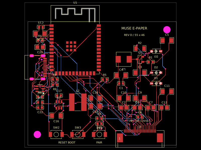 More from this authormuse/esp32-eink-displayA 55×46 mm two-layer ESP32-S3 e-paper controller board with USB‑C power/programming, buck regulation, FPC display connector, UC8179-style boost/charge-pump circuitry, ESD protection, controls, and routed passive components.
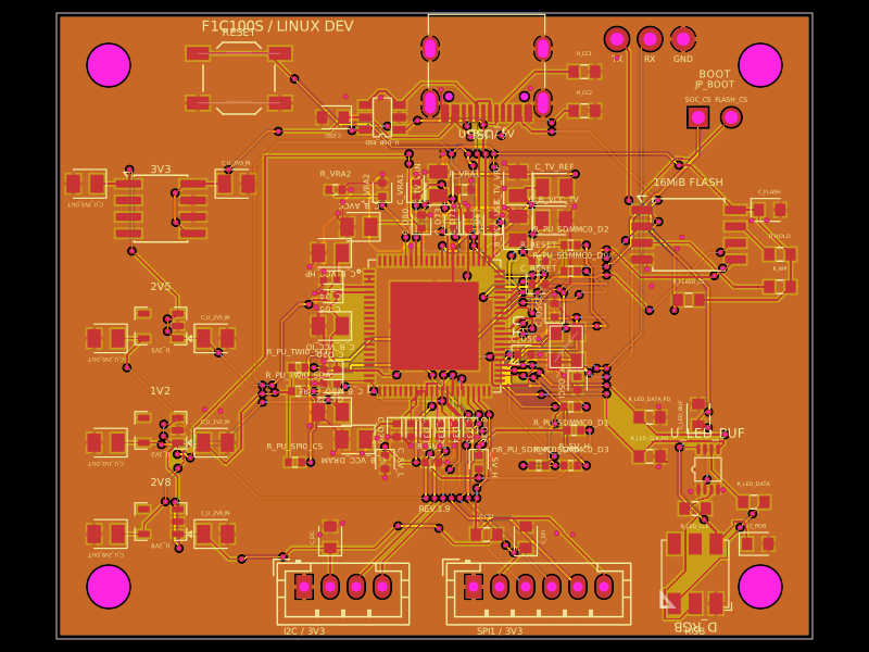 Discover something newseveibar/f1c100s-linux-dev-boardA 4-layer F1C100S Linux development carrier board with USB‑C power/data, multi-rail LDOs, SPI NOR flash, reset/boot interfaces, I²C/SPI/UART headers, ESD protection, and a buffered 5‑V clocked RGB LED.