muse/book-reading-clip-lamp
A 60‑mm ESP32‑S3 lamp-head PCB combining USB‑C battery charging/power regulation, OV5640 autofocus camera interfacing, I²S microphone and differential speaker audio, six‑LED boost-driven reading light, buttons, status indicators, and battery monitoring.
- Version
- 0.2.5
- License
- unset
- Stars
- 0
camera-sourcing.txt
Schematic

LAMP CLIP REV B - CAMERA SOURCING AND CONNECTION
05 October 2026 | Selected engineering part; no samples purchased or tested

CAMERA TO REQUEST
Manufacturer: Kai Lap Technologies Group Ltd. (KLT)
Exact part: KLT-PAA40-OV5640-1B V1.0 ESP32
Product: https://kailaptech.com/product.aspx?id=3122&l1=712
Drawing: https://kailaptech.net/KLT/EN/PDF/KLT-PAA40-OV5640-1B%20V1.0%20ESP32%205MP%20OmniVision%20OV5640-1B%20DVP%20Parallel%20Interface%20ESP32%20Auto%20Focus%20Camera%20Module.pdf
Sales contact published by manufacturer: Sales@KaiLapTech.com
Order route: request a sample/production quotation directly from KLT.
No current price, MOQ, stock or lead time is verified. No message or order was sent.

Request the standard 21.25 mm version, not the separately listed 45 mm variant.
This is the autofocus lens/sensor assembly on its own flex ribbon, with embedded
VCM driver. It does not require the Adafruit breakout daughterboard. Confirm the
supplier includes the complete camera and flex, rather than a loose sensor IC.
Ask for the current controlled drawing, sample availability, MOQ, lead time,
unit pricing, autofocus initialization details, and focus performance at 20-30 cm.
Confirm the shipped pinout matches the 2023-10-14 drawing page 7, especially
pin10=DVDD 1.5 V, pin23=NC, pin24=AFVDD 2.8 V. Do not substitute another OV5640
flex merely because it has 24 contacts. A changed variant needs a fresh audit.

WHY IT MATCHES THIS BOARD
U1 is ESP32-S3-WROOM-1U-N16R8 (16 MB flash / 8 MB PSRAM).
The camera is OV5640-1B, 5 MP (2592 x 1944), 8-bit DVP parallel output.
Espressif's esp32-camera driver supports ESP32-S3 and OV5640:
https://github.com/espressif/esp32-camera
This is interface/pinout compatibility, not a completed hardware validation.
It is not a MIPI-CSI camera. Raspberry Pi CSI cameras cannot substitute here.
The main PCB now supplies 2.8 V AVDD/DOVDD/AFVDD and 1.5 V DVDD, with signal
translation. Muse still needs the board-specific JPEG capture backend.

MATCHING CONNECTOR J2
Hirose FH12-24S-0.5SH(55), LCSC/JLC C202112.
https://www.lcsc.com/product-detail/C202112.html
https://www.hirose.com/product/p/CL0586-0521-0-55
24 signal contacts, 0.5 mm pitch, bottom contacts, 0.3 mm-thick flex, horizontal
insertion, front flip-lock; 16.1 x 6.4 x 2.0 mm connector body.
The camera manufacturer explicitly specifies the FH12-24S-0.5SH mating family.
The footprint and connector 3D model are imported from JLCSearch, locally frozen.
The 24-land span is11.5 mm at0.5 mm pitch; the imported0.28 x1.40 mm
signal lands fit the Hirose catalog0.30+/-0.03 x1.30+/-0.10 mm range.
Hold-down pad geometry follows the JLC library; confirm solder fillet/stencil
with the assembler against the controlled Hirose drawing before fabrication.
Additional footprint terminals 25/26 are grounded mechanical hold-downs, not
camera contacts. The camera's pin23 remains unconnected.

MECHANICAL FIT
Published lens block: 8.5 x 8.5 x 5.07 mm; flex overall length 21.25 mm.
The wider connector contact tail is 12.5 mm in the camera drawing.
Place J2 on the bottom/page side and route the flex inward toward the lens.
The 9 x 9 mm silkscreen box is a provisional lens alignment region only, not
an enclosure datum. Reserve room to lift the latch, insert the flex and retain
the lens on a separate nonconductive support. No tension or bending at the lens
bond. Lens/flex 3D geometry is not supplied; only J2's connector model is included.
With power removed, open the latch, insert the flex fully with exposed contacts
against the connector's bottom contact beams, then close the latch evenly.
Verify pin1 orientation against the controlled camera and connector drawings;
mirrored PCB views are not a wiring instruction. Never hot-plug this camera.

BRING-UP
Verify 3.3 V, 2.8 V and 1.5 V before inserting a camera. U9 enable follows the
2.8 V rail; this is not a power-good supervisor. Scope the actual rail ramps
and confirm the required rail ordering/timing before a hardware release.
R30/R31 hold clock/reset low; R32 holds powerdown high during MCU reset. U10/U11
outputs are disabled while CAM_PWDN is high. U12 translates XCLK/reset/powerdown
to 2.8 V. U13 translates SCCB, has internal pull-ups, and enables with RESET_N.
Keep powerdown high/reset low until rails are stable, start external XCLK,
release powerdown then reset with the sensor's required delays, and probe SCCB.
Use sensor/driver documented clock and divider settings; do not assume the old
Adafruit onboard oscillator or VM jumper exists. Enable PSRAM, start with one
JPEG frame buffer, load the matching autofocus firmware and test focus before
page capture. Validate PCLK/data timing and tune R33 from oscilloscope results.
2.8 V and 1.5 V remain on in camera standby while the 3.3 V rail is on; this
revision does not provide independent camera-rail power gating.

Read camera-pinout.csv for every contact and pin-map.csv for ESP32 GPIOs.
Related Packages
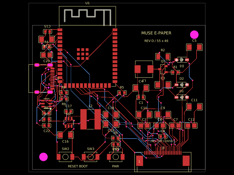 More from this authormuse/esp32-eink-displayA 55×46 mm two-layer ESP32-S3 e-paper controller board with USB‑C power/programming, buck regulation, FPC display connector, UC8179-style boost/charge-pump circuitry, ESD protection, controls, and routed passive components.
 Discover something newastra/pd-power-supplyUSB-PD Power Supply with RP2040 controller