README.md
# 18 W USB-C PD mains charger prototype

This tscircuit project implements an isolated USB-C Power Delivery source for a nominal US 120 Vac branch circuit. It is intentionally a bench/prototype PCB, not a finished plug-in consumer product: mains enters through a 600 Vac direct wire-clamp terminal rather than integral NEMA blades, and the board requires a certified enclosure and independent safety review.

## Electrical target

- Input: 85–305 Vac through a 1 A / 250 V fuse and 14D471K MOV.
- Isolation: Mean Well IRM-20-24 encapsulated AC/DC module, 24 V / 0.9 A / 21.6 W.
- USB-PD output: 5 V / 3 A, 9 V / 2 A, 12 V / 1.5 A, 15 V / 1.2 A, or 20 V / 0.9 A; 18 W maximum.
- PD/control: STUSB4710A standalone source controller.
- Regulation: ST1S14 buck converter with the resistor ladder used by ST's STEVAL-ISC004V1 reference design.
- VBUS switching/protection: back-to-back Si4925DDY P-channel MOSFETs, CC-line ESD protection, and ESDA25P35 VBUS surge protection.
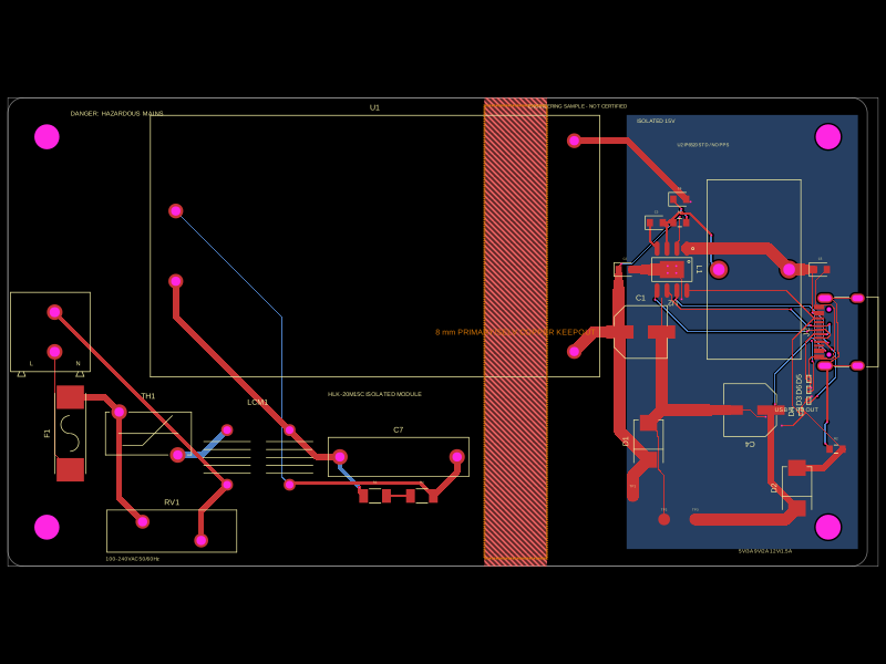
- Board: 136 mm × 52 mm, two layers, 0.60/0.30 mm vias, manually routed top-layer mains copper, and an 8 mm copper-free primary/SELV corridor under the encapsulated module.
- AC terminal: TE Connectivity 282838-2 (JLCPCB C5168775), 2-position direct wire-to-board screw clamp, 10 mm pitch, 13.5 A, 600 Vac, rotated with its side-entry openings facing the left board edge.

The feedback ladder produces approximately 5.02, 9.04, 12.03, 15.01, and 19.99 V from the ST1S14's 1.22 V reference. The STUSB4710A NVM must advertise matching PDOs before a USB-C sink is attached.

## Status

- TypeScript passes `bunx tsc --noEmit`.
- tscircuit build contains 113 source connections, 90 routed PCB traces, 61 vias, and zero generated DRC error records.
- The complete schematic is on one A4 landscape `schematicsheet`, divided into six functional `schematicsection` cells, with no elements outside the sheet.
- Gerbers include top/bottom copper, mask, paste, silkscreen, edge cuts, plated and non-plated drill files, BOM, and pick-and-place CSV.
- The generated KiCad archive is included for inspection, but KiCad 10's CLI crashed while attempting DRC on the exported board. Treat the Gerbers and circuit-json as the authoritative generated artifacts.
- STEP export completes, but tscircuit reports that several imported component STEP models could not be parsed; mechanical fit must be checked from vendor drawings and the 3D preview, not the STEP file alone.

## Safe low-voltage bring-up

R12 is a removable 0 Ω link between the AC/DC module output and the low-voltage electronics. For initial testing, leave the AC input disconnected, remove R12, and inject an isolated, current-limited 24 V supply at J4:

- J4 pin 1: VIN24
- J4 pin 2: GND
- J3 pin 1: GND
- J3 pin 2: 3V3
- J3 pin 3: SDA
- J3 pin 4: SCL

See `PD_PROGRAMMING.md` and `FABRICATION_CHECKLIST.md` before ordering or powering a board.

## Build and export

```sh
bun install
bunx tsc --noEmit
tsci build --all-images --autorouter-timeout 120s --ignore-warnings --disable-parts-engine
tsci export dist/index/circuit.json -f gerbers -o dist/usb-c-pd-wall-charger-gerbers.zip --disable-parts-engine
```

The parts engine is disabled because it produced a low-confidence footprint substitution during development. Exact imported LCSC/EasyEDA footprints are committed under `imports/`.

## Reference documents

- ST STEVAL-ISC004V1 user manual: https://www.st.com/resource/en/user_manual/um2293-getting-started-with-the-stevalisc004v1-evaluation-board-for-the-stusb4710a-usb-pd-controller-with-onboard-dcdc-stmicroelectronics.pdf
- STUSB4710A datasheet: https://www.st.com/content/ccc/resource/technical/document/datasheet/group3/2f/24/4e/67/ed/d6/4b/af/DM00383615/files/DM00383615.pdf/jcr%3Acontent/translations/en.DM00383615.pdf
- ST1S14 datasheet: https://www.st.com/resource/en/datasheet/st1s14.pdf
- Mean Well IRM-20 specification: https://www.meanwell.com/Upload/PDF/IRM-20/IRM-20-SPEC.PDF

## Non-negotiable limitations

Do not connect this open PCB directly to a wall outlet. A fabricated board is still not a certified charger. Before any mains test, a qualified engineer must review creepage/clearance, protective components, enclosure, accessible-metal bonding, thermal behavior, abnormal operation, hipot/leakage, conducted/radiated emissions, and the exact component safety approvals. A commercial product also needs the applicable UL/ETL, FCC, USB-IF, and mechanical/blade compliance work.