README.md
# USB3 SD hub — engineering draft 0.1.5

**Not fabrication ready. Do not order the diagnostic Gerbers.**

This update preserves one female USB-C host socket, two USB-C accessory sockets, two USB-A accessory sockets and one full-size SD socket. It uses computer power only and does not provide USB Power Delivery charging to the host. No extra port or power input was added. Available computer power limits which peripheral combinations can operate.

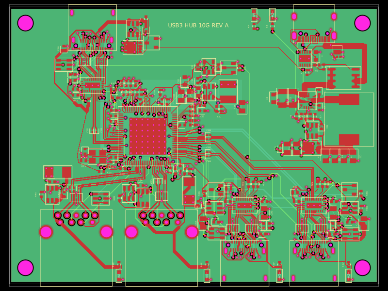
The PCB outline is 86 × 68 mm, four layers and nominally 1.6 mm thick. Assembly parts are on top. Inner1 and inner2 are ground references. The design targets the selected JLCPCB JLC04161H-3313 controlled-impedance profile; final fabricator acceptance and USB qualification are still required.

## Current progress

- Eleven initial hub pair sections are routed: 22 signal trace records, using the local tscircuit router for five short sections and explicitly saved, checked paths for six longer sections. The complete board is not routed.
- Those sections pass nine geometric checks, a 0.127 mm pair skew limit and the documented conservative 2 mm uncoupled-length check. This is not an electrical simulation or whole-board release.
- The complete partial-routing snapshot still reports **770 unconnected PCB ports**. USB connector-side sections, USB-A paths, USB2 paths, SD signals, power and other connections remain to be completed and checked.
- Exactly three schematic sheets are generated: Host and Power; Hub and USB Ports; Full-size SD Reader. No `schX` or `schY` props are authored in the board source.
- All 229 assembly parts have manufacturer part numbers. USB-C sockets are Amphenol 12401610E4#2A and USB-A sockets are Amphenol GSB311131HR; the earlier discontinued socket selections have been replaced.
- Board and populated-assembly STEP files, a native GLB, an outline/drill DXF and editable CAD export code are included. Component models are nominal; fit, tolerances and assembly rotations are not qualified.

## Files and builds

Edit **index.circuit.tsx**. `index.tsx` is a compatibility export. `tscircuit.config.json` selects only the real board entry, so verification JSON cannot become the package preview.

`bun install` installs the pinned dependencies. `bun run typecheck` checks production source. `bun run build:preview` produces the placement preview and all three schematics with routing disabled. The public preview therefore does not represent completion of routing. `bun run build:routing` runs the full local routing plan; cloud autorouting is disabled.

`verification/partial-routing.circuit.json` and its PCB/GLB views contain the actual 22 routed traces and retained unconnected-port errors. `verification/rebuild-partial-review.tsx` rebuilds only the eleven defined routing sections, with remaining routing disabled explicitly. `verification/check-partial-routes.ts` checks those sections; `pair-geometry-check.json` records the result and exact snapshot hash. `validation-summary.json` records the full error and warning counts.

The `cad/` directory contains the board and populated assembly STEP, DXF and CAD validity report. See its README for units, datums, model provenance and limits. `verification/NOT-FOR-FABRICATION-partial-gerbers.zip` is a diagnostic export, with an independent parser report and layer preview.

## Before fabrication

Complete every connection and USB pair constraint, then rerun whole-board connectivity, clearance, coupling, skew and return-path checks. Finish hub/reader configuration images, bus-powered descriptors, unused-port settings, pre-enumeration and suspend power, inrush, overload and reverse-current review. Qualify every footprint, part availability, effective capacitor value, soldering process and assembly rotation. Check final routed Gerbers and prototype USB/power behavior.

The stencil has no apertures on plated connector lands and uses 60% windowed paste coverage on the two main QFN exposed pads. Connector stakes and USB-A pins need a separate soldering operation. Via-in-pad locations require filled/capped processing and stencil review; tenting alone is not filling. The small signal vias use 0.45 mm pads / 0.20 mm holes. These process choices still need manufacturing qualification, including the USB-C shell-post mounting on the selected 1.6 mm PCB.

The first downstream USB-C hub-to-multiplexer TX and RX polarities are intentionally inverted. USB3 automatically detects/corrects this; see the [Microchip USB5816C hardware checklist, section 4](https://ww1.microchip.com/downloads/aemDocuments/documents/UNG/ProductDocuments/DesignChecklist/USB5816C-Hardware-Design-Checklist-DS00004191.pdf). The schematic and checked routing use the same mapping.

TOOL-ISSUES.md separates historical tool reproductions and already tracked defects from unfinished board engineering. No GitHub issue or PR was filed for this update. No components were ordered.