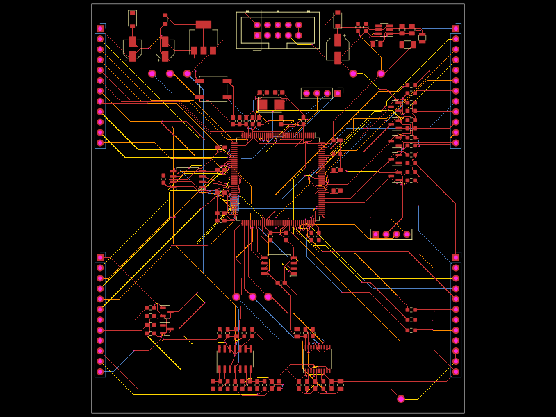
A 64 mm STM32F405 flight-controller PCB with ICM-42688 IMU, SPI flash, USB-C/ESD, battery buck and 3.3 V regulation, four motor outputs, service I/O, and PETG standoff mounting hardware.
# Flight controller V2 with native tscircuit assembly
The 64 × 64 mm, four-layer FC is in `index.circuit.tsx`. Open `assembly.circuit.tsx` and select **3D** for the complete mounting view. The assembly uses `assembly.device`, `assembly.printedpart`, `assembly.referencesurface`, `assembly.subassembly` and `assembly.part`; it includes the real routed board rather than a substitute model.

## Mounting assembly
- PETG prototype base: 72 × 72 × 2 mm, with a 42 × 42 mm central opening.
- Four integrated hollow posts use the existing outer **56 × 56 mm** mounting pattern. The inner 30.5 mm pattern remains unused.
- Post tips are 12 mm above the base bottom, leaving **10 mm clearance** between base top and PCB underside.
- Printed through bores: 3.4 mm. PCB holes remain 3.2 mm.
- Four nominal M3 × 18 nylon screws, 0.5 mm washers and M3 nylon nuts. Their models omit threads and drive recesses; obtain actual hardware separately and verify fit before use.
- Print `mount/fc-v2-mount.stl` base-down, in millimetres. Check bore fit and use nylon hardware without overtightening. No support is expected for the upright posts, but slicer settings and print tolerances require a trial print.
This is a prototype FC mount, not a complete drone frame or qualified vibration isolator. No physical fit, temperature, vibration or flight-load test has been performed. Choose isolation appropriate to the actual gyro and airframe after bench testing.
## Build and inspect
```sh
npm install
npm run build
npm run check:assembly
```
The site includes the standalone PCB and its assembly. The mounting face places mechanical parts around the board's existing position; PCB copper and layout remain unchanged. `validation/mount-assembly.json` records a direct comparison of pads, holes, vias, traces, pours and paste, plus solid-geometry checks at the actual emitted PCB mounting holes. The same CAD plan generates the printable STL.
The build retains existing electrical/style advisories, including a requested 0.25 mm connection reported as 0.15 mm and a long non-45-degree segment. Publishing this assembly does not resolve those advisories or constitute a new manufacturing sign-off. The completed-build checks are in `validation/publish-native-checks.json`; partial CLI checks on JSON are not supported by this pinned toolchain.
## Fabrication and use
The original prototype JLCPCB files remain under `manufacturing/jlcpcb/`. The printed mount and nylon hardware are separate purchases, outside the SMT BOM. The board is for the existing 3S prototype system; firmware, power, receiver/ESC wiring and first-article tests remain required. Never connect motor current through the FC or its jumper headers. Assembly geometry does not establish flight readiness.
Native assembly API reference: [tscircuit assembly.device](https://docs.tscircuit.com/elements/assembly-device).