README.md
# NEMA23 controller — reference feature parity, revision E

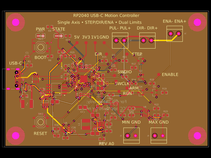
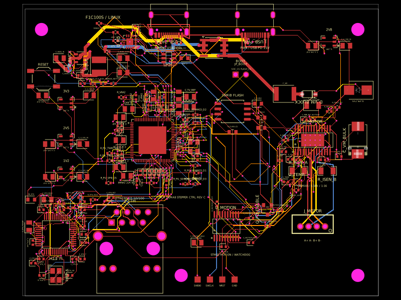
Revision E / 1.2.3-local updates the published v1.1.0 NEMA23 board for the 23HS30-2804S-H motor. Feature comparison uses `imrishabh18/rp2040-motor-controller` v1.0.42 (retrieved 2026-10-02). This package is a PCB design. Neither reference includes executable motor firmware; application behavior still requires firmware.

The 57 × 57 mm four-layer outline, provisional 47.14 mm mounting pattern, DRV8452DDWR, approximately 3.965 A peak / 2.804 A RMS nominal current setting, 28 V EPR capability, independent logic USB port, JST-XH motor connector, eFuse, bulk capacitor and hardware temperature/power-good interlock are retained.

## Feature comparison

| Reference function | NEMA23 revision E implementation |
|---|---|
| USB programming, BOOT/RUN, SWD, QSPI flash | Existing RP2040 subsystem retained |
| STEP/DIR motor control | DRV8452DDWR (C5624514), STEP/DIR and SPI wiring retained |
| Software-selectable motor USB-PD | CH224Q I2C control of 5/9/12/15/20/28 V requests; 5 V leaves the motor rail disabled |
| Temperature readings and application alerts | Existing TMP102 at 0x48; independent hardware interlock retained as an additional feature |
| Actual winding-current readings | Two INA240A1DR amplifiers and separate 10 mΩ, 1 W shunts; GPIO28/29 ADC inputs |
| Multicolor status | LTST-C19HE1WT RGB LED, three DTC114 transistor sinks, three 1 kΩ resistors; powered from fixed logic USB 5 V |
| Audible alarm | HYG-8503A buzzer, AO3400A switch, flyback diode, gate pull-down and bypass capacitor |
| Optional shaft encoder | AS5600 at the board origin on the bottom; sensor and both local bypass capacitors unpopulated |
| Voltage probing | TP_PD (raw negotiated supply), TP_VMOTOR (protected rail), TP_PD_GND |
| Independent power indicator | Original logic power LED retained |

The reference's low-profile 50 V bulk capacitor and PH motor connector are not substituted for the NEMA23's reservoir and higher-current XH harness. Those are mechanical/component choices, not missing user functions. NEMA23 remains a different power stage and requires its own firmware pin mapping and current calibration.

## Current measurement

R_PHASE_A and R_PHASE_B are Vishay WSLP1206R0100FEA / C844910, 10 mΩ ±1%, 1 W. Each sits in series with the positive-named output of one motor winding, separate from the DRV8452's integrated regulation sensing. INA240A1 input branches start at the shunt pads. REF1 connects to 3.3 V and REF2 to GND.

Nominal transfer: `V_ADC = 1.65 V + I_phase × 0.2 V/A`. At ±4 A the outputs are 0.85–2.45 V. Positive current flows from the driver-side shunt pad to the connector-side pad. The 1 kΩ / 10 nF ADC filters have a nominal 15.9 kHz corner. Shunt dissipation is 0.16 W at 4 A DC (about 0.079 W at 2.81 A RMS), before thermal derating. This range differs from the reference's 1 V/A; its calibration constants must not be reused.

The ADC measures actual bidirectional winding current. This alone does not establish shaft position. The optional encoder needs a fitted chip, both capacitors, an aligned diametrically magnetized shaft magnet and application support.

## Programmable USB-PD

The existing 210 kΩ CFG1 resistor still requests 28 V at motor-port attachment, independently of MCU firmware. The motor remains disconnected until POWER_ARM is asserted. This differs from the reference board's 5 V default; all requested voltage selections are available in software after boot.

CH224Q supports the following writes to register 0x0A at its detected 7-bit address 0x22 or 0x23:

| Value | Requested voltage |
|---:|---:|
| 0 | 5 V standby; motor rail blocked |
| 1 | 9 V |
| 2 | 12 V |
| 3 | 15 V |
| 4 | 20 V |
| 5 | 28 V EPR |

Read 0x09 for negotiated-protocol status and 0x50 for available contract current in 50 mA units. Requests depend on the source's advertised capabilities. Do not treat a register write as proof of a successful contract. Do not request PPS/AVS or voltages above 28 V in this design.

The eFuse UVLO and PGOOD upper divider resistors change from 190 kΩ to 51 kΩ, giving a nominal 7.32 V rising threshold. This permits 9–28 V operation while rejecting 5 V fallback. The 30.36 V nominal OVP, 2.46 A nominal input limit, output slew limit, fuse and blocking diode remain. A lower supply reduces the available input power; it does not reduce the programmed phase-current target automatically. Require a source/current contract that covers the intended load and eFuse-limit tolerance. 28 V needs a suitable EPR source and genuine EPR cable.

GPIO4/5 implement I2C0, shared by the optional AS5600 on the MCU side and CH224Q through TCA9517DGKR. Both buffer supplies use logic 3.3 V. Its powered-off high-impedance bus pins isolate CH224Q's internal pull-ups when the logic USB is absent. GPIO8 enables the buffer; a 100 kΩ pull-down disables it during reset. Keep it disabled when motor USB is absent, including when using the encoder with logic power alone. R_ENC_SDA/SCL are the populated 4.7 kΩ MCU-side pull-ups; the PD-side pull-ups are internal to CH224Q. Start at 100 kHz and verify bus rise time and power sequencing on hardware. The TMP102 remains on a separate I2C1 bus.

During any voltage change, stop motion and set ARM, WAKE and POWER_ARM low. Let the isolated motor rail discharge before lowering voltage: the blocking diode prevents the charger from sinking its stored charge, and the retained 220 µF / 10 kΩ network has a nominal 2.2 s time constant. Require a fresh valid contract, PD_PG_N low, sufficient contract current, no fault and acceptable temperature before enabling the eFuse and then the driver. Do not automatically restart after a fault or renegotiation.

## Firmware pin mapping

| RP2040 GPIO | Signal |
|---:|---|
| 0 | POWER_ARM — eFuse enable, default low |
| 1 | PD_PG_N — active-low PD power-good |
| 2 | POWER_FAULT_N — active-low eFuse fault |
| 3 | BUZZER_PWM |
| 4 / 5 | I2C0 SDA / SCL — encoder and buffered PD control |
| 6 | WAKE — DRV8452 nSLEEP, default low |
| 7 | HOME_N — driver electrical home indication |
| 8 | PD_BUS_ENABLE — I2C buffer enable, default low |
| 10 / 11 / 25 | RGB green / blue / red |
| 16 / 17 / 18 / 19 | SPI0 MISO / CS / SCK / MOSI |
| 20 / 21 | STEP / DIR |
| 22 | ARM — driver-enable request, default low |
| 23 | FAULT_N — DRV8452 fault |
| 24 | TEMP_OK — combined TMP102 ALERT / eFuse PGOOD |
| 26 / 27 | I2C1 SDA / SCL — TMP102 |
| 28 / 29 | ADC2 / ADC3 — winding A / B current |

GPIO28/29 no longer carry WAKE/HOME. GPIO25 no longer drives the removed single-color LED. The original reference firmware is not pin compatible.

At startup keep POWER_ARM, ARM, WAKE, PD_BUS_ENABLE and BUZZER_PWM low. Detect/configure TMP102 and implement temperature thresholds, communication-failure handling and watchdog recovery before arming. For motor-body mounting, initial bring-up thresholds are current foldback at 60 °C, latched shutdown at 70 °C and explicit re-arm only below 55 °C, pending measured thermal correlation. Configure TMP102 ALERT in active-low comparator mode with 70 °C T_HIGH and 55 °C T_LOW before enabling motion; firmware must additionally enforce the 60 °C foldback and sensor-health checks. These are requirements; executable firmware is not included. Read the sensor even though its ALERT also gates the driver. Absence of a pulled-low ALERT is not evidence of a healthy sensor.

Validate the PD contract, enable the eFuse, wait for PGOOD, wake the driver, verify SPI and set motor-specific current while ARM remains low. Only then allow motion. On any power, sensor or driver fault, latch off ARM/WAKE/POWER_ARM and require a new explicit arm request. Use RGB and buzzer signals for application-defined status; the magnetic buzzer requires a PWM waveform. Allow about 120 mA extra 3.3 V load while sounding and validate regulator heating.

## Mechanical and power limits

The four 5.2 mm mounting holes and 8 mm screw-head clearances are provisional. Verify the actual motor rear-face pattern, shaft/bearing boss, standoffs, magnet and cable exit. The optional encoder may require a rear shaft and magnet arrangement absent on the original motor. Factory-populated parts remain on top; U_ENCODER and its two local capacitors are DNP on the bottom. The original 220 µF / 63 V capacitor remains approximately 25 mm tall.

The selected [23HS30-2804S-H motor](https://www.omc-stepperonline.com/nema-23-high-temp-stepper-motor-1-85nm-256-9oz-in-insulation-class-h-180c-23hs30-2804s-h) is specified at 2.81 A per phase, 1.13 Ω, 4.8 mH, 1.85 Nm and 1.8° per step. It has a single shaft. The 180 °C figure describes its winding insulation class; it is not an allowable controller temperature. The controller will be motor-body mounted: use thermally insulating standoffs and an air gap, keep all pads clear of the metal housing, and retain airflow around the components. The 47.14 mm pattern has not been confirmed as a rear mounting pattern for this motor; verify rear fasteners and cable clearance using the supplied mounting template. The optional AS5600 remains DNP because this motor has no accessible rear shaft.

R_REF_TOP = 2.61 kΩ and R_REF_BOT = 10 kΩ, both specified at ±1%, give VREF = 2.617 V. At TI's nominal KV = 0.66 V/A, full scale is 3.965 A peak / 2.804 A RMS for sinusoidal microstepping. The motor's 2.81 A RMS corresponds to 3.974 A peak. Both the previous DRV8462DDW and requested DRV8452DDW have a 5 A full-scale / 3.5 A RMS IC rating; the new current setting, telemetry range and thermal validation are necessary for this motor. The DDW and PWP versions are not interchangeable. Current-setting tolerances mean the divider is not an accurate safety limiter.

Before ARM goes high, keep VREF_INT_EN = 0 and program TRQ_DAC. Begin at 0x7F (50% scale, approximately 1.40 A RMS nominal). Until current is calibrated, cap TRQ_DAC at 0xEB: with ±2% logic rail, ±1% divider resistors and TI's minimum KV = 0.625 V/A, its calculated upper bound is 2.796 A RMS. After calibration, approach the required current only while respecting a measured 2.81 A RMS motor limit, harness temperature, the thermal foldback and the available power budget. Do not enable the internal reference or use auto-torque/custom current profiles to bypass these limits. The hardware defaults keep the driver disabled; no firmware implementing this sequence is supplied. See `engineering/motor-profile.json` for checked design and bring-up parameters.

The motor connector remains 1 A+ (black), 2 A− (green), 3 B+ (red), 4 B− (blue), per the motor drawing. Verify winding pairs and connector orientation when crimping. Use an XHP-4 housing, SXH-001T-P0.6 contacts and 22 AWG wire. JST rates XH at 3 A with 22 AWG, with an 85 °C operating ceiling including temperature rise. Motor-body mounting requires derating and measured contact temperature; the 4 A instantaneous sine peak does not imply a 4 A RMS connector rating.

At rated current, winding copper loss alone is about 17.85 W at the stated 1.13 Ω, before winding resistance rises with temperature. A 9 V input at the retained 2.46 A nominal eFuse limit offers only 22.1 W before losses. Start full-load evaluation with a suitable 20 V or 28 V contract and derate current/speed for lower-voltage contracts; full torque at every 9–28 V setting is not established. The 2.46 A limit applies to the supply, not phase current.

The DRV8452 is rated to 55 V operating / 60 V absolute maximum (TI Rev. B). D_TVS is now Littelfuse SMBJ33A / C224019, 33 V standoff and 53.3 V clamp at its rated 11.3 A pulse, replacing SMBJ36A. Validate switching overshoot and regeneration at operating temperature; the TVS is not a continuous braking load. Board input remains 28 V maximum.

The new driver's EasyEDA land pattern is rotated 90° into the existing board orientation. Its 44 lead lands and 7.6 × 3.4 mm exposed pad replace the previous footprint; all 18 ground thermal vias fit within the new pad. Retained 1.2 mm phase trunks require 2 oz outer copper. Filled/plugged thermal vias, solder coverage, copper thickness and enclosure airflow need assembly review and thermal tests. No continuous full-current rating is claimed for an untested board on a hot motor.

Every supply rail, charge-pump connection and motor output is routed on top/bottom copper only. GND and signals may use the inner layers. `routing/power-layer-policy.json` defines the rails, and `scripts/check-power-layers.mjs` audits the built copper before release. The motor supply/output trunks retain explicit wide paths. The added shunts are not bypassed by the original trunks. Preserve their distinct driver-side and winding-side nets and dedicated sense branches when editing routing. The blocking diode and TVS do not provide sustained regenerative braking capability.

## Board markings

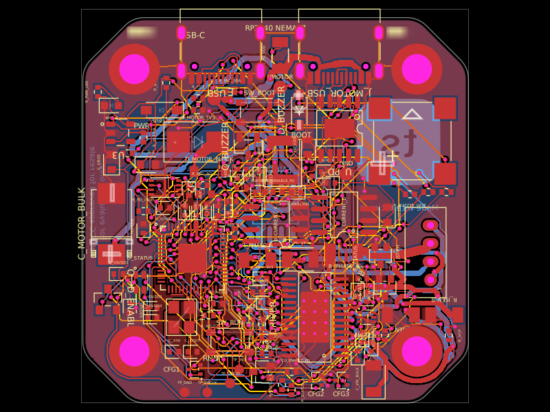
Both sides identify the programming USB-C port as DATA and the motor-supply USB-C port as PWR. The front labels sit beside the connector shells; the underside labels sit between their mounting stakes. Rear silkscreen also carries the reference board's tscircuit logo and attribution, the NEMA23 / RP2040 name, revision E prototype marking, and evaluation-only notice. `board-markings.tsx` contains these additions. These markings remain present after the driver, routing and symbol updates.

`previews/pcb-top.png` and `previews/pcb-bottom.png` show each physical side with solder mask. The bottom preview is flipped for reading from beneath the board. Assembly fabrication notes are omitted from these two artwork previews because they are not printed silkscreen; `previews/pcb.png` retains the combined engineering view.

## Imported symbols and native schematic layout

The installed releases checked on 2026-10-02 are tscircuit 0.0.2729, CLI 0.1.2228 and easyeda-converter (`easyeda`) 0.0.364. The lockfile also resolves core 0.0.2050 and capacity-autorouter 0.0.951.

All integrated circuits use tscircuit's native yellow chip boxes, including RP2040, DRV8452, flash, regulators, amplifiers and interface ICs. Their physical footprints and pin mappings remain imported. The 10 remaining non-IC part definitions retain their supplier schematic drawings generated with EasyEDA-converter. `bun scripts/reimport-symbols.mjs` regenerates those drawings from cached raw EasyEDA records and explicitly excludes the native IC and USB-C types listed in `engineering/schematic-style.json`. The generator preserves physical pin aliases and footprint numbering, including the programming connector's split shell contacts. Raw data and hashes are in `engineering/easyeda/`.

Both USB-C ports use `<connector standard="usb_c" />` with the native USB artwork, signal pins on the right and shell pins below. Supplier footprints, physical contact numbers and connections are retained. `usb-c-compat.ts` extends the native power/ground rows to expose all four VBUS and all four GND contacts on the 20-contact motor-power receptacle; core 0.0.2050 otherwise draws only two of each. Pin placement and artwork remain native, and the two schematic boxes are sized to keep their labels clear.

Every schematic sheet uses standard A4 (297 × 210 mm). Dense pages are split by function, and each section has a short explanation rendered as native schematic text. Native tscircuit autolayout places all components; component positions are not fixed with `schX`/`schY`. Section membership, automatic grids, margins and orientation are the layout hints. Coordinates in `imports/symbols` describe the remaining non-IC symbol artwork itself. Source and build audits reject fixed component positions, imported IC artwork, non-A4 pages and content outside the drawing area.

Compatibility adjustments address the current core's Circuit JSON symbol import: inward stem metadata preserves supplier pin labels; diode artwork is normalized to vertical local orientations; and `symbol-text-compat.ts` attaches reference/value text to its owner and suppresses inherited resistor pin names. Transistor references sit beside their local drawings to avoid collector labels. None of these changes places circuit components manually.

Decoupling capacitors form compact native grids (3 × 2 for IOVDD, 3 × 1 for the core rail and 2 × 2 for logic bypass). The two current-sense channels have separate functional groups, each retaining its own local bypass capacitor. Native match-pack places these groups automatically. `schematic-section-notes.ts` also preserves explicit native grid layout when children belong to a schematic section, working around core 0.0.2050 overriding the grid. Every schematic-analysis finding fails the release check; no findings are waived.

## Build and verification

Use Bun, Node.js, and uv (the copper audits use Python with pinned Shapely 2.1.2):

```sh
bun install --frozen-lockfile
bun run typecheck
./node_modules/.bin/tsci check netlist index.circuit.tsx
./node_modules/.bin/tsci check schematic-placement index.circuit.tsx
./node_modules/.bin/tsci check placement index.circuit.tsx
bun scripts/regenerate-routing.mjs  # only after PCB connectivity/geometry changes
bun run check:release
```

Saved routes are fingerprinted against the input geometry and connectivity. Do not weaken that guard. `verify:built` checks the original power/interlock behavior and added ADC, RGB, alarm, test point, shared I2C and DNP connections. It also verifies the physical sense-trace endpoints. `check:release` includes independent DRC, Gerber-derived shorts, physical ground connectivity and Kelvin copper separation checks. See verification.md for the current run; archived v1.0.8 results do not validate revision E.

The saved routing includes local clearance repairs, direct shunt-pad sense branches, and a copper bridge between the BOOT switch's grounded contacts. The current toolchain resolves autorouter 0.0.951. The saved plan also includes the outer-layer power routing and clearance repairs required by the updated checker. Fresh autorouting must be reviewed and pass all checks before replacing this plan.

No physical prototype of this revision has been tested. Current calibration, PWM rejection, regulator load, temperature response, EPR interoperability, startup/voltage transitions and mechanical fit need bench validation before manufacturing or use.

## Local preview

In the delivered folder, run `bun install --frozen-lockfile` and then `node start-preview.mjs`. This starts the latest installed CLI on port 3020 with Canvas rendering by default. The current experimental WebGPU renderer rejects through-pad traces. The launcher changes only the renderer default in a disposable copy of the bundled viewer, using the CLI's `RUNFRAME_STANDALONE_FILE_PATH` override; it does not modify installed packages or circuit data. The adapter stops for review if the expected bundle signature changes.

The ordinary `bun run dev` command also works, but its viewer defaults to WebGPU. To switch manually, right-click the PCB and choose **Rendering Engine → Canvas**.

## Source references

- [Original NEMA23 board](https://tscircuit.com/imrishabh18/nema-23-stepper-controller), v1.0.8, release 43dc48be-737b-4dce-a6fd-4a68a8465ed2.
- [Feature reference](https://tscircuit.com/imrishabh18/rp2040-motor-controller), v1.0.42, release e8d285f7-c3d8-46f5-9a54-344fdde0124e.
- [WCH CH224 datasheet](https://www.wch-ic.com/downloads/CH224DS1_PDF.html), sections 5.2.3 and 6.1.1.
- [TI INA240](https://www.ti.com/lit/ds/symlink/ina240.pdf), [DRV8452](https://www.ti.com/lit/ds/symlink/drv8452.pdf), [TPS2663](https://www.ti.com/lit/ds/symlink/tps2663.pdf), [TCA9517](https://www.ti.com/lit/ds/symlink/tca9517.pdf).
- [Motor current convention](https://help.omc-stepperonline.com/hc/s/articles/how-to-set-the-current-on-stepper-driver-rms-or-peak), [JST XH ratings](https://www.jst-mfg.com/product/pdf/eng/eXH.pdf), [Littelfuse SMBJ33A](https://www.littelfuse.com/products/overvoltage-protection/tvs-diodes/surface-mount/smbj/smbj33a).
- [Vishay WSLP shunt](https://www.vishay.com/docs/30122/wslp.pdf).
- Imported parts for RGB, alarm, INA240 and AS5600 come from the published reference. Existing vendored RP2040 licensing is retained.

Section explanations use native schematic text. `schematic-section-notes.ts` wraps these annotations to their section width and places them above the rendered rail and trace labels. It derives note positions from autolayout bounds and never changes component or wire placement.