imrishabh18/nema-23-stepper-controller
A 57 mm four-layer RP2040 NEMA23 stepper-controller PCB with USB‑C/USB‑PD power input, protected motor rail, DRV8452 dual-winding driver, bidirectional current sensing, temperature/enable interlock, optional magnetic encoder, RGB LED and buzzer status indicators, and motor/test connectors.
- Version
- 1.2.3
- License
- unset
- Stars
- 0
feature-parity.tsx
import { Fragment } from "react";
import { INA240A1DR } from "./imports/INA240A1DR";
import { WSLP1206R0100FEA } from "./imports/WSLP1206R0100FEA";
import { LTST_C19HE1WT } from "./imports/LTST_C19HE1WT";
import { DTC114EU3HZGT106 } from "./imports/DTC114EU3HZGT106";
import { HYG_8503A } from "./imports/HYG_8503A";
import { AO3400A } from "./imports/AO3400A";
import { B5819W_SL } from "./imports/B5819W_SL";
import { AS5600_ASOM } from "./imports/AS5600_ASOM";
// INA240A1 gain 20 V/V × 10 mΩ = 0.2 V/A: 0.85–2.45 V at ±4 A.
// Unlike the reference's 50 mΩ shunts, these retain ADC headroom at NEMA23 current.
export function FeatureParity() {
    return <>
  <schematicsheet sheetSize="A4" name="current" displayName="Bidirectional winding-current telemetry" sheetIndex={12}>
    <schematicsection name="current_A" displayName="Phase A — measures winding current at 0.2 V/A"/>
    <schematicsection name="current_B" displayName="Phase B — measures winding current at 0.2 V/A"/>
  </schematicsheet>
  <group name="CURRENT_SENSE" pcbRelative schAutoLayoutEnabled schSheetName="current">
  {(["A", "B"] as const).map((phase, i) => {
            const s = { schSheetName: "current", schSectionName: `current_${phase}` };

            const x = i ? 22 : -5, y = i ? -16.7 : -23;
            return <group key={phase} name={`CURRENT_${phase}`} pcbRelative schAutoLayoutEnabled schMarginTop={2.5} schSheetName="current">
      <WSLP1206R0100FEA name={`R_PHASE_${phase}`} pcbX={i ? 14 : -1.7} pcbY={i ? -17.4 : -18} pcbRotation={i ? 0 : 180} schRotation={90} schMarginX={1.0} schMarginY={1.0} {...s} connections={{ pin1: `net.${phase}_DRIVE`, pin2: `net.${phase}_PLUS` }}/>
      <INA240A1DR name={`U_CURRENT_${phase}`} pcbX={x} pcbY={y} pcbRotation={i ? 90 : 270} {...s} connections={{ VS: "net.V3V3", REF1: "net.V3V3", REF2: "net.GND", GND: "net.GND", NC: "net.GND", OUT: `net.CURRENT_${phase}_RAW` }}/>
      {/* Dedicated sense branches start at the resistor pads, separate from the power trunks. */}
      <trace name={`SENSE_${phase}_POS`} from={`.R_PHASE_${phase} > .pin1`} to={`.U_CURRENT_${phase} > .IN_POS`} thickness={0.15} maxViaCount={0} schDisplayLabel={`${phase}_DRIVE`}/>
      <trace name={`SENSE_${phase}_NEG`} from={`.R_PHASE_${phase} > .pin2`} to={`.U_CURRENT_${phase} > .IN_NEG`} thickness={0.15} maxViaCount={0} schDisplayLabel={`${phase}_PLUS`}/>
      <capacitor schMarginX={0.35} schMarginY={0.7} name={`C_CURRENT_${phase}`} capacitance="100nF" footprint="0402" supplierPartNumbers={{ jlcpcb: ["C1525"] }} pcbX={i ? 27 : -10} pcbY={i ? -17 : -22} pcbRotation={i ? 90 : 0} schOrientation="vertical" {...s} connections={{ pin1: "net.V3V3", pin2: "net.GND" }}/>
      <resistor schMarginX={0.35} schMarginY={0.7} name={`R_ADC_${phase}`} resistance="1k" footprint="0402" supplierPartNumbers={{ jlcpcb: ["C11702"] }} pcbX={i ? -5 : -5} pcbY={i ? -0.8 : -2.5} {...s} connections={{ pin1: `net.CURRENT_${phase}_RAW`, pin2: `net.CURRENT_${phase}` }}/>
      <capacitor schMarginX={0.35} schMarginY={0.7} name={`C_ADC_${phase}`} capacitance="10nF" footprint="0402" supplierPartNumbers={{ jlcpcb: ["C15195"] }} pcbX={i ? -3 : -3} pcbY={i ? -0.8 : -4.3} schOrientation="vertical" {...s} connections={{ pin1: `net.CURRENT_${phase}`, pin2: "net.GND" }}/>
    </group>;
        })}
  </group>
  <schematicsheet sheetSize="A4" name="status" displayName="RGB status and audible alarm" sheetIndex={14}>
    <schematicsection name="rgb" displayName="Status LED — displays firmware-selected states"/>
    <schematicsection name="alarm" displayName="Alarm — switches the buzzer from a PWM signal"/>
  </schematicsheet>
  <LTST_C19HE1WT name="D_STATUS" pcbX={-24} pcbY={5} schSheetName="status" schSectionName="rgb" connections={{ _POS: ".MCU .J_USB .A4B9" }}/>
  {(["R", "G", "B"] as const).map((color, i) => {
            const s = { schSheetName: "status", schSectionName: "rgb" };
            const y = [13, 9, 1][i];
            return <Fragment key={color}>
      <DTC114EU3HZGT106 name={`Q_STATUS_${color}`} pcbX={-24} pcbY={y} {...s} connections={{ B: `net.LED_${color}`, E: "net.GND" }}/>
      <resistor schMarginX={1.0} schMarginY={1.2} name={`R_STATUS_${color}`} resistance="1k" footprint="0402" supplierPartNumbers={{ jlcpcb: ["C11702"] }} pcbX={-26.5} pcbY={y} pcbRotation={90} schOrientation="vertical" {...s} connections={{ pin1: `.D_STATUS > .${color}_NEG`, pin2: `.Q_STATUS_${color} > .C` }}/>
    </Fragment>;
        })}
  <HYG_8503A name="BZ1" pcbX={-21} pcbY={-10.3} schSheetName="status" schSectionName="alarm" noConnect={["NC1", "NC2"]} connections={{ _POS: "net.V3V3", _NEG: "net.BUZZER_SINK" }}/>
  <AO3400A name="Q_BUZZER" pcbX={-20} pcbY={-17.5} schSheetName="status" schSectionName="alarm" connections={{ D: "net.BUZZER_SINK", S: "net.GND", G: "net.BUZZER_GATE" }}/>
  <B5819W_SL name="D_BUZZER" pcbX={-24.4} pcbY={-17} schRotation={0} schSheetName="status" schSectionName="alarm" connections={{ anode: "net.BUZZER_SINK", cathode: "net.V3V3" }}/>
  <resistor schMarginX={0.35} schMarginY={0.7} name="R_BUZZER_GATE" resistance="100" footprint="0402" pcbX={-17} pcbY={-17} pcbRotation={180} schSheetName="status" schSectionName="alarm" connections={{ pin1: "net.BUZZER_PWM", pin2: "net.BUZZER_GATE" }}/>
  <resistor schMarginX={0.35} schMarginY={0.7} name="R_BUZZER_PD" resistance="100k" footprint="0402" pcbX={-17} pcbY={-19} schOrientation="vertical" schSheetName="status" schSectionName="alarm" connections={{ pin1: "net.BUZZER_GATE", pin2: "net.GND" }}/>
  <capacitor schMarginX={0.35} schMarginY={0.7} name="C_BUZZER" capacitance="10uF" maxVoltageRating="10V" footprint="0603" pcbX={-25} pcbY={-4} schOrientation="vertical" schSheetName="status" schSectionName="alarm" connections={{ pin1: "net.V3V3", pin2: "net.GND" }}/>
  <schematicsheet sheetSize="A4" name="encoder" displayName="Optional shaft encoder (unpopulated)" sheetIndex={15}>
    <schematicsection name="encoder" displayName="Optional encoder — reads shaft angle over I2C"/>
  </schematicsheet>
  <AS5600_ASOM name="U_ENCODER" doNotPlace layer="bottom" pcbX={0} pcbY={0} schSheetName="encoder" schSectionName="encoder" noConnect={["OUT", "PGO"]} connections={{ VDD5V: "net.V3V3", VDD3V3: "net.V3V3", GND: "net.GND", DIR: "net.GND", SDA: "net.I2C0_SDA", SCL: "net.I2C0_SCL" }}/>
  {(["SDA", "SCL"] as const).map((pin, i) => <resistor schMarginX={0.35} schMarginY={0.7} key={pin} name={`R_ENC_${pin}`} resistance="4.7k" footprint="0402" pcbX={-1} pcbY={i ? 10.5 : 9} schOrientation="vertical" schSheetName="encoder" schSectionName="encoder" connections={{ pin1: "net.V3V3", pin2: `net.I2C0_${pin}` }}/>)}
  {(["100nF", "1uF"] as const).map((value, i) => <capacitor schMarginX={0.35} schMarginY={0.7} key={value} name={i ? "C_ENCODER_BULK" : "C_ENCODER"} doNotPlace layer="bottom" capacitance={value} footprint="0402" pcbX={i ? -1 : 1} pcbY={4.4} schOrientation="vertical" schSheetName="encoder" schSectionName="encoder" connections={{ pin1: "net.V3V3", pin2: "net.GND" }}/>)}
  <schematicsheet sheetSize="A4" name="test_access" displayName="Power measurement access" sheetIndex={16}>
    <schematicsection name="test_access" displayName="Test pads — expose input power, VM and ground"/>
  </schematicsheet>
  {([['TP_PD', 'VIN', 25, -9], ['TP_VMOTOR', 'VM', 25, -3], ['TP_PD_GND', 'GND', 25, -6]] as const).map(([name, net, x, y], i) => <Fragment key={name}>
    <testpoint name={name} footprintVariant="pad" padShape="circle" padDiameter="1.5mm" pcbX={x} pcbY={y} schSheetName="test_access" schSectionName="test_access" connections={{ pin1: `net.${net}` }}/>
    <silkscreentext text={net} pcbX={x} pcbY={y + 1.3} fontSize={0.65}/>
  </Fragment>)}
    </>;
}
Related Packages
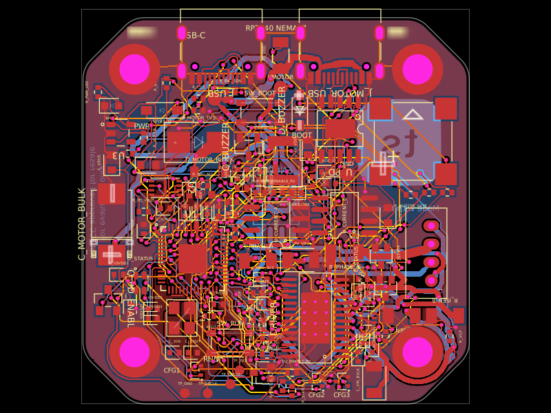 More from this authorimrishabh18/rp2040-motor-controllerA 4-layer RP2040-based USB-C/USB-PD controller board that powers and drives a NEMA17 stepper via a DRV8825, with current/temperature telemetry, RGB and buzzer status indicators, QSPI flash, protection/filtering, test points, and optional AS5600 encoder support.
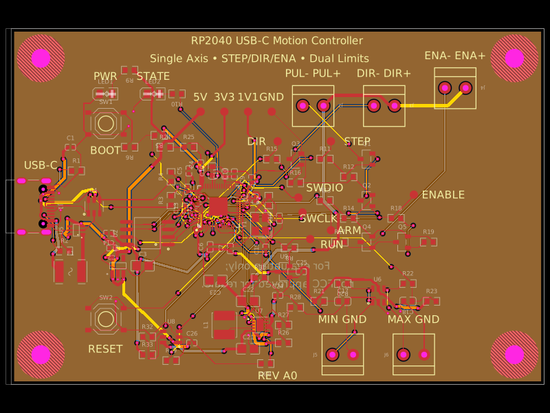 Similar packageAnasSarkiz/rp2040-usb-c-single-axis-dm542t-motion-controller--01a0e89cA USB‑C RP2040 controller board with external QSPI flash, crystal clock, regulated 3.3/1.1/5 V power, boost-converted motor-driver supply, protected USB and limit inputs, status LEDs, reset/boot switches, and AO3400A MOSFET outputs for stepper-control signals.
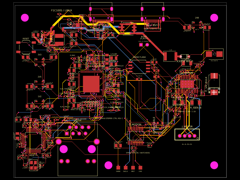 Discover something newshibosoftwaredev/f1c100s-linux-nema8-stepper-controllerA four-layer Linux motion-control carrier board combining an Allwinner F1C100S SoC, USB-C PD power, 10/100 Ethernet, STM32 watchdog-controlled DRV8825 NEMA-8 stepper drive, SPI flash, regulated power rails, USB protection, and supporting connectors/passives.