imrishabh18/nema-23-stepper-controller
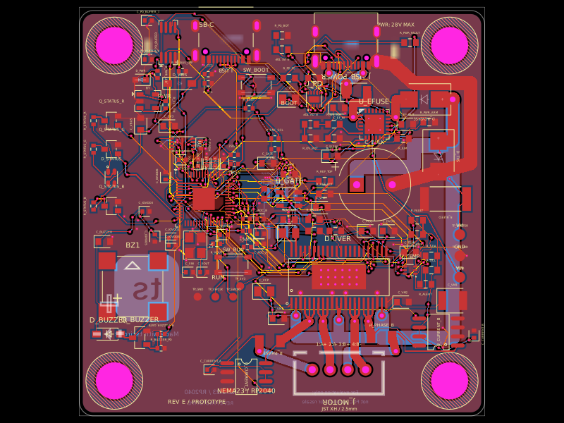
A 57 mm four-layer RP2040 NEMA23 stepper-controller PCB with USB‑C/USB‑PD power input, protected motor rail, DRV8452 dual-winding driver, bidirectional current sensing, temperature/enable interlock, optional magnetic encoder, RGB LED and buzzer status indicators, and motor/test connectors.
- Version
- 1.2.3
- License
- unset
- Stars
- 0
index.circuit.tsx
PCB
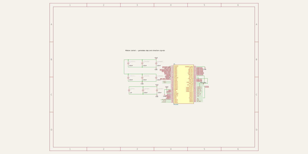
Schematic
import "./usb-c-compat"
import "./symbol-text-compat";
import "./schematic-section-notes";
import { Microcontroller_RP2040 } from "./vendor/rp2040";
import { DRV8452DDWR } from "./imports/DRV8452DDWR";
import { UsbPdPower } from "./usb-pd-power";
import { B4B_XH_A_LF__SN_ } from "./imports/B4B_XH_A_LF__SN_";
import { TMP102AIDRLR } from "./imports/TMP102AIDRLR";
import { SN74LVC1G08DBVR } from "./imports/SN74LVC1G08DBVR";
import { Passives } from "./passives";
import { PowerCopper } from "./power-copper";
import { FeatureParity } from "./feature-parity";
import { savedRouting } from "./routing/saved-routing";
import { BoardMarkings } from "./board-markings";
// Rear screw pattern is motor-specific. Verify before fabrication.
export const mechanical = { width: 57, height: 57, mountPitch: 47.14, holeDiameter: 5.2 };
const power = { schSheetName: "power", schSectionName: "power" };
const driver = { schSheetName: "driver", schSectionName: "driver" };
const thermal = { schSheetName: "thermal", schSectionName: "thermal" };
export const driverNets: Record<string, string> = {
    pin1: "VCP", pin2: "VM", pin3: "GND", pin4: "A_DRIVE", pin5: "A_DRIVE", pin6: "A_DRIVE",
    pin7: "A_MINUS", pin8: "A_MINUS", pin9: "A_MINUS", pin10: "GND", pin11: "VM", pin12: "VM",
    pin13: "GND", pin14: "B_MINUS", pin15: "B_MINUS", pin16: "B_MINUS",
    pin17: "B_DRIVE", pin18: "B_DRIVE", pin19: "B_DRIVE", pin20: "GND", pin21: "VM", pin22: "GND",
    pin23: "GND", pin24: "DVDD", pin25: "V3V3", pin26: "FAULT_N", pin27: "HOME_N", pin28: "V3V3",
    pin33: "VREF", pin34: "SPI_CS", pin36: "SPI_MISO", pin37: "SPI_MOSI", pin38: "SPI_SCK",
    pin39: "STEP", pin40: "DIR", pin41: "ENABLE_SAFE", pin42: "WAKE", pin43: "CPL", pin44: "CPH", pin45: "GND",
};
export const gpioNets: Record<string, string> = {
    GPIO0: "POWER_ARM", GPIO1: "PD_PG_N", GPIO2: "POWER_FAULT_N",
    GPIO3: "BUZZER_PWM", GPIO4: "I2C0_SDA", GPIO5: "I2C0_SCL",
    GPIO6: "WAKE", GPIO7: "HOME_N", GPIO8: "PD_BUS_ENABLE",
    GPIO10: "LED_G", GPIO11: "LED_B", GPIO25: "LED_R",
    GPIO16: "SPI_MISO", GPIO17: "SPI_CS", GPIO18: "SPI_SCK", GPIO19: "SPI_MOSI",
    GPIO20: "STEP", GPIO21: "DIR", GPIO22: "ARM", GPIO23: "FAULT_N", GPIO24: "TEMP_OK",
    GPIO26_ADC0: "TEMP_SDA", GPIO27_ADC1: "TEMP_SCL", GPIO28_ADC2: "CURRENT_A", GPIO29_ADC3: "CURRENT_B",
};
export default function Nema23Controller({ routingDisabled = false, routingAlgorithm = savedRouting }: {
    routingDisabled?: boolean;
    routingAlgorithm?: any;
} = {}) {
    return <board width={mechanical.width} height={mechanical.height} borderRadius={2} thickness={1.6} layers={4} routingDisabled={routingDisabled} pcbRelative schAutoLayoutEnabled isViaInPadAllowed minViaHoleDiameter={0.2} minViaPadDiameter={0.4} minPadEdgeToPadEdgeClearance={0.15} minViaEdgeToPadEdgeClearance={0.17} autorouterVersion="beta_pipeline7" autorouterEffortLevel="2x" autorouter={{ local: true, groupMode: "subcircuit", ...(routingAlgorithm ? { algorithmFn: routingAlgorithm } : {}) }}>
    <net name="GND"/><net name="V3V3"/>
    <schematicsheet sheetSize="A4" name="controller" displayName="RP2040 controller" sheetIndex={1}/>
    <schematicsheet sheetSize="A4" name="controller_programming" displayName="USB data interface" sheetIndex={2}>
      <schematicsection name="MCU__usb" displayName="Data USB — connects the controller to a host"/><schematicsection name="MCU__usb_series" displayName="USB termination — damps data-line reflections"/>


    </schematicsheet>
    <schematicsheet sheetSize="A4" name="power" displayName="Motor Power — USB-C to VM" sheetIndex={7}>
      <schematicsection name="power" displayName="Motor supply — protects and filters the VM rail"/>


    </schematicsheet>
    <schematicsheet sheetSize="A4" name="driver" displayName="DRV8452 stepper driver" sheetIndex={11}><schematicsection name="driver" displayName="Motor driver — regulates current in both windings"/></schematicsheet>
    <schematicsheet sheetSize="A4" name="thermal" displayName="Temperature and enable interlock" sheetIndex={13}><schematicsection name="thermal" displayName="Interlock — permits motion only when armed and cool"/></schematicsheet>
    <schematicsheet sheetSize="A4" name="logic_supply" displayName="Logic power and decoupling" sheetIndex={4}>
      <schematicsection name="MCU__programming_supply" displayName="Logic supply — converts USB power to 3.3 V"/>

      <schematicsection name="MCU__programming_bypass" displayName="Supply bypass — supplies fast local current"/>
    </schematicsheet>
<schematicsheet sheetSize="A4" name="flash" displayName="RP2040 firmware storage" sheetIndex={3}>
      <schematicsection name="MCU__programming_flash" displayName="QSPI flash — stores RP2040 firmware"/>
    </schematicsheet>
<schematicsheet sheetSize="A4" name="power_settings" displayName="Motor power protection settings" sheetIndex={9}>
      <schematicsection name="power_protection" displayName="eFuse controls — set current limit and ramp time"/>
      <schematicsection name="uvlo" displayName="UVLO — blocks an insufficient input supply"/>
      <schematicsection name="ovp" displayName="OVP — disconnects an excessive input voltage"/>
      <schematicsection name="power_good" displayName="Power good — confirms the motor rail is ready"/>
    </schematicsheet>
<schematicsheet sheetSize="A4" name="usb_pd" displayName="USB-PD voltage negotiation" sheetIndex={8}>
      <schematicsection name="usb_pd" displayName="USB-PD — negotiates the motor supply voltage"/>
    </schematicsheet>
<schematicsheet sheetSize="A4" name="controller_support" displayName="Controller clock, boot and reset" sheetIndex={5}>

    </schematicsheet>
<schematicsheet sheetSize="A4" name="controller_aux" displayName="Analog supply and power indicator" sheetIndex={6}>

    </schematicsheet>
    <schematicsheet sheetSize="A4" name="controller_debug" displayName="SWD debug access" sheetIndex={17}/>
    <Microcontroller_RP2040 name="MCU" schAutoLayoutEnabled pcbRelative pcbX={-11} pcbY={1.5} schSheetName="controller"/>
    <trace name="COMMON_GROUND" from=".MCU .U1 .GND" to="net.GND" thickness={0.3} schDisplayLabel="GND"/>
    <trace name="LOGIC_SUPPLY" from=".MCU > .L_AVDD > .pin1" to="net.V3V3" thickness={0.3} schDisplayLabel="V3V3"/>
    {Object.entries(gpioNets).map(([pin, net]) => <trace key={pin} from={`.MCU .U1 .${pin}`} to={`net.${net}`} schDisplayLabel={net} thickness={0.15}/>)}

    <UsbPdPower />
    <diode schMarginX={0.35} schMarginY={0.7} name="D_REVERSE" manufacturerPartNumber="SS510B" supplierPartNumbers={{ jlcpcb: ["C65011"] }} pinLabels={{ pin1: ["cathode", "neg"], pin2: ["anode", "pos"] }} footprint="smb" pcbX={20} pcbY={16} pcbRotation={180} schRotation={90} {...power} connections={{ anode: ".U_EFUSE > .OUT1", cathode: "net.VM" }}/>
    <diode schMarginX={0.35} schMarginY={0.7} name="D_TVS" manufacturerPartNumber="SMBJ33A" supplierPartNumbers={{ jlcpcb: ["C224019"] }} pinLabels={{ pin1: ["cathode", "neg"], pin2: ["anode", "pos"] }} footprint="smb" pcbX={22} pcbY={8} pcbRotation={270} schRotation={90} {...power} connections={{ cathode: ".D_REVERSE > .cathode", anode: "net.GND" }}/>
    <capacitor schMarginX={0.35} schMarginY={0.7} name="C_BULK" capacitance="220uF" maxVoltageRating="63V" manufacturerPartNumber="EEU-FR1J221L" footprint="electrolytic_d10mm_p5mm" pcbX={13} pcbY={4} schOrientation="vertical" {...power} connections={{ pin1: ".D_TVS > .cathode", pin2: "net.GND" }}/>
    <resistor schMarginX={0.35} schMarginY={0.7} name="R_BLEED" resistance="10k" footprint="2512" pcbX={23} pcbY={2} pcbRotation={180} schOrientation="vertical" {...power} connections={{ pin1: ".C_BULK > .pin1", pin2: "net.GND" }}/>

    <DRV8452DDWR name="DRIVER" pcbX={8} pcbY={-9} {...driver} noConnect={["pin29", "pin30", "pin31", "pin32", "pin35"]}/>
    {Object.entries(driverNets).map(([pin, net]) => <trace key={pin} from={`.DRIVER > .${pin}`} to={`net.${net}`} schDisplayLabel={net} thickness={0.25}/>)}
    <B4B_XH_A_LF__SN_ name="J_MOTOR" pcbX={8} pcbY={-22} pcbRotation={180} {...driver} connections={{ pin1: "net.A_PLUS", pin2: "net.A_MINUS", pin3: "net.B_PLUS", pin4: "net.B_MINUS" }}/>
    <Passives />
    <FeatureParity />
    <PowerCopper />
    <TMP102AIDRLR schMarginX={1.1} name="U_TEMP" pcbX={18} pcbY={-8} {...thermal} connections={{ SCL: "net.TEMP_SCL", SDA: "net.TEMP_SDA", ALERT: "net.TEMP_OK", GND: "net.GND", ADD0: "net.GND", V_POS: "net.V3V3" }}/>
    <SN74LVC1G08DBVR schMarginX={1.1} name="U_GATE" pcbX={1} pcbY={2} {...thermal} connections={{ A: "net.ARM", B: "net.TEMP_OK", Y: "net.ENABLE_SAFE", VCC: "net.V3V3", GND: "net.GND" }}/>
    {[-1, 1].flatMap(x => [-1, 1].map(y => <group key={`${x}:${y}`} pcbX={0} pcbY={0}>
      <hole diameter={mechanical.holeDiameter} pcbX={x * mechanical.mountPitch / 2} pcbY={y * mechanical.mountPitch / 2}/>
      <silkscreencircle radius={4} pcbX={x * mechanical.mountPitch / 2} pcbY={y * mechanical.mountPitch / 2}/>
      <keepout shape="circle" radius={4} pcbX={x * mechanical.mountPitch / 2} pcbY={y * mechanical.mountPitch / 2}/>
    </group>))}
    <copperpour name="GND_TOP" layer="top" connectsTo="net.GND" clearance={0.25} boardEdgeMargin={0.5} coveredWithSolderMask/>
    <copperpour name="GND_BOTTOM" layer="bottom" connectsTo="net.GND" clearance={0.25} boardEdgeMargin={0.5} coveredWithSolderMask/>
    <silkscreentext text="NEMA23 / RP2040" pcbX={-5} pcbY={-25} fontSize={0.9}/>
    <silkscreentext text="PWR: 28V MAX" pcbX={16} pcbY={26.5} fontSize={0.7}/>
    <silkscreentext text="1:A+ 2:A- 3:B+ 4:B-" pcbX={8} pcbY={-18.4} fontSize={0.65}/>
    <silkscreentext text="JST XH / 2.5mm" pcbX={8} pcbY={-27.5} fontSize={0.65}/>
    <silkscreentext text="REV E / PROTOTYPE" pcbX={-12} pcbY={-26.5} fontSize={0.8}/>
    <BoardMarkings />
  </board>;
}
Related Packages
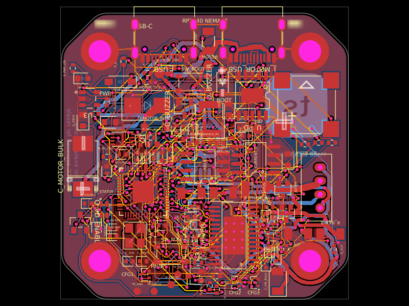 More from this authorimrishabh18/rp2040-motor-controllerA 4-layer RP2040-based USB-C/USB-PD controller board that powers and drives a NEMA17 stepper via a DRV8825, with current/temperature telemetry, RGB and buzzer status indicators, QSPI flash, protection/filtering, test points, and optional AS5600 encoder support.
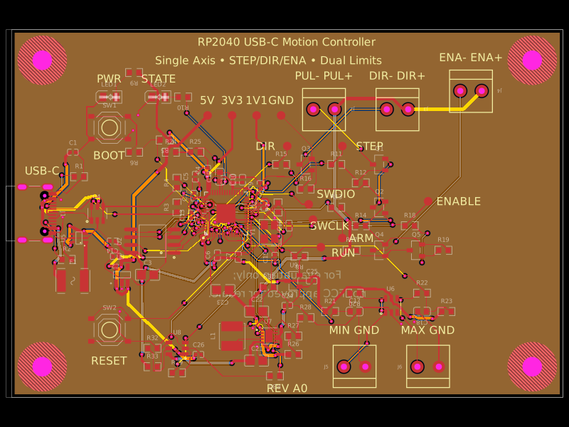 Similar packageAnasSarkiz/rp2040-usb-c-single-axis-dm542t-motion-controller--01a0e89cA USB‑C RP2040 controller board with external QSPI flash, crystal clock, regulated 3.3/1.1/5 V power, boost-converted motor-driver supply, protected USB and limit inputs, status LEDs, reset/boot switches, and AO3400A MOSFET outputs for stepper-control signals.
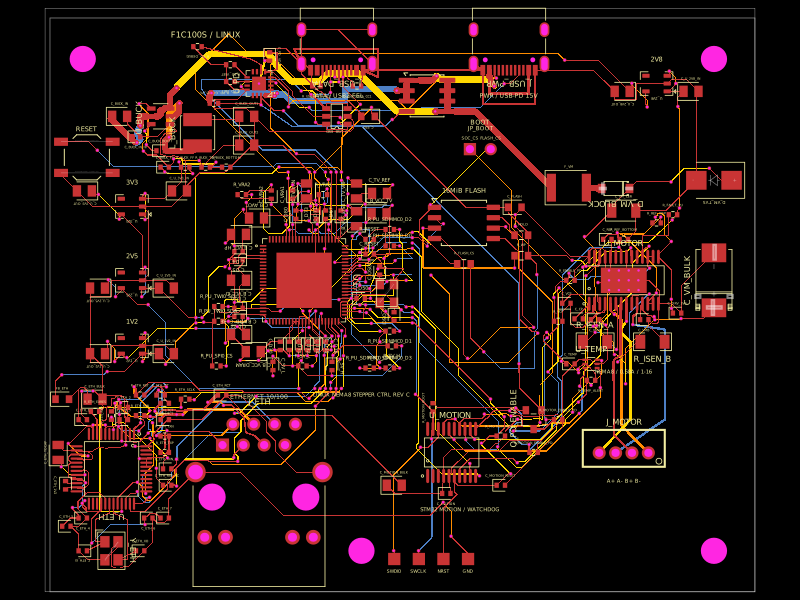 Discover something newshibosoftwaredev/f1c100s-linux-nema8-stepper-controllerA four-layer Linux motion-control carrier board combining an Allwinner F1C100S SoC, USB-C PD power, 10/100 Ethernet, STM32 watchdog-controlled DRV8825 NEMA-8 stepper drive, SPI flash, regulated power rails, USB protection, and supporting connectors/passives.