mohan-bee/flight-controller-v2
A 64 mm STM32F405 flight-controller PCB with ICM-42688 IMU, SPI flash, USB-C/ESD, battery buck and 3.3 V regulation, four motor outputs, service I/O, and PETG standoff mounting hardware.
- Version
- 0.1.0
- License
- ISC
- Stars
- 0
manufacturing/jlcpcb/README.md
PCB

Schematic
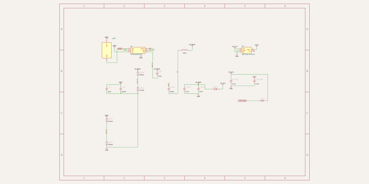
# FC V2 — jumper receiver connection

Upload fabrication.zip, BOM.csv and CPL.csv separately to JLCPCB. Use a 64 × 64 mm, four-layer, 1.6 mm FR-4 board, 1 oz outer copper, standard inner copper, ENIG, green mask and top-side assembly. Keep the supplied unit outline; request factory tooling rails as needed. Copper order is top / inner1 / inner2 ground / bottom. Through vias are 0.25 mm drill / 0.5 mm land.

The 67 SMT assembly positions have been checked against supplier pad numbering and placement origins. J_RX is a hand-installed 1×4 male 2.54 mm header, with 1 mm holes and 1.8 mm lands. J_BAT, J_SWD, J_AUX and J_M1–J_M4 remain exposed wire pads. These seven connectors and J_RX are excluded from SMT assembly and stencil paste. No bottom assembly is required.

Four corner M3 holes are 4 mm inward from each edge, on a 56 mm square. Four additional M3 holes retain the 30.5 mm stack pattern for the receiver. All mounting holes are 3.2 mm unplated. The USB connector has four plated slots and two locating holes. Choose one mounting pattern; eight screws are unnecessary.

## Receiver wiring

J_RX is on the right edge. Pin 1 is the square land nearest the lower edge. Top-view coordinates and signals:

| Pin | Coordinate, mm | Signal | Receiver J_LINK |
|---|---|---|---|
| 1 | (27, −7.81) | regulated 5 V output | pin 1 |
| 2 | (27, −5.27) | GND | pin 2 |
| 3 | (27, −2.73) | FC UART receive | pin 3, RC_OUT |
| 4 | (27, −0.19) | FC UART transmit | leave open for the initial mLRS configuration |

Use three female-to-female jumpers initially. The receiver's fourth J_LINK pin is its separate serial UART input, not the return leg of the RC_OUT UART. Do not connect it expecting stock mLRS bidirectional CRSF telemetry. Use J_SERIAL and the FC auxiliary UART for separately configured serial telemetry, or implement compatible custom firmware before enabling the fourth wire. UART signaling is 3.3 V.

Power the FC from the existing 3S battery input (12.6 V fully charged). Do not feed an independent 5 V BEC into the receiver while its 5 V jumper is connected to the FC. Servo power is supplied separately to the receiver's J_SERVO_POWER; it must not enter the FC 5 V rail.

## Checks and remaining qualification

Native circuit errors, independent copper clearance, physical connectivity, supplier placement and final Gerber geometry/drill/mask/stencil/silkscreen checks pass. Gerbers and CPL use the board-centre origin, millimetres, X right / Y up. Review the factory placement preview against pcb.png before confirming an order. No order has been submitted.

This is a prototype submission package. A custom Betaflight 4.5.2 target now compiles; firmware, regulator loading with the receiver attached, noise, USB, sensors, motor outputs and flight behavior still require powered bench validation. See the accompanying firmware/README.md in drone-preorder-handoff.zip for HEX files, FlySky/custom-receiver profiles, OneShot125 wiring and programming pin order. There is no onboard ESC. Battery reverse-polarity and harness-transient protection are not included on the PCB; the harness guide requires keyed polarity, short wiring and an external low-ESR bulk capacitor, followed by transient measurement. The original FC V1 release is preserved separately.
Related Packages
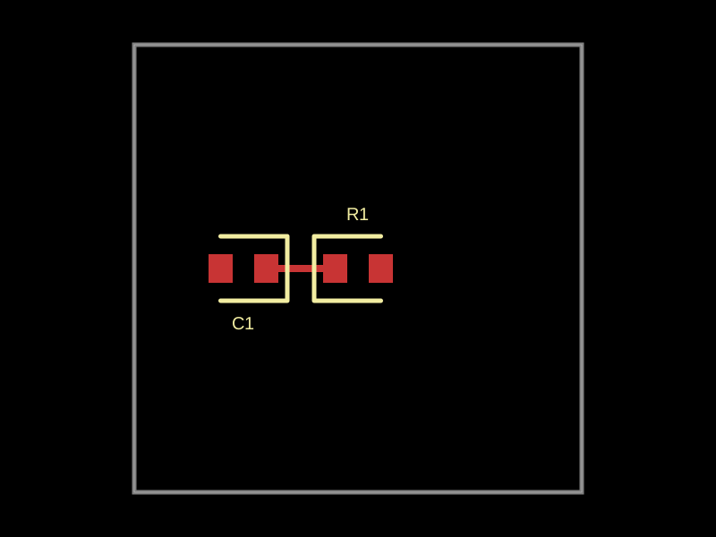 More from this authormohan-bee/repro-2This code defines a 10x10mm circuit board featuring a 1kΩ resistor and a 1000pF capacitor connected via 0402 footprint components.
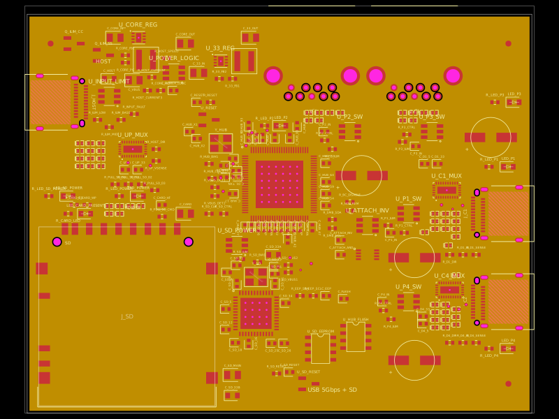 Similar packagegokul/usb3-sd-hubEngineering draft: four-layer, computer-powered USB 3 hub with one USB-C host socket, two USB-C and two USB-A accessory sockets, and a full-size SD slot. Board and three schematic previews are available. Routing and production checks are incomplete; not fabrication ready.
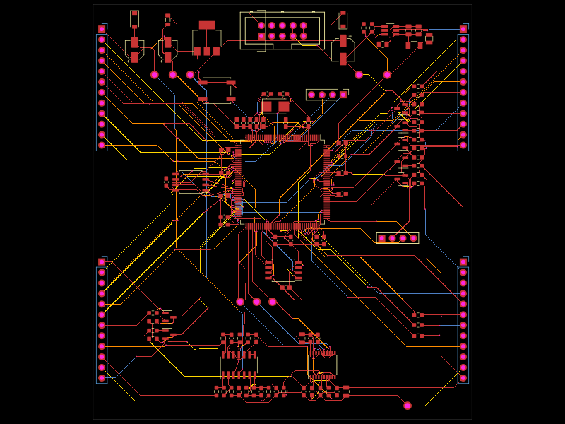 Discover something newhrithik18k/punck-tscircuit-recreationA four-layer Eurorack drum/sampler controller PCB built around an STM32H743, dual QSPI flash, PCM5100 stereo DAC, TL074 analog audio circuitry, input clamps, 12V-to-3.3V power regulation, MIDI/USB/SWD connectors, controls, LEDs, and trigger/audio I/O.