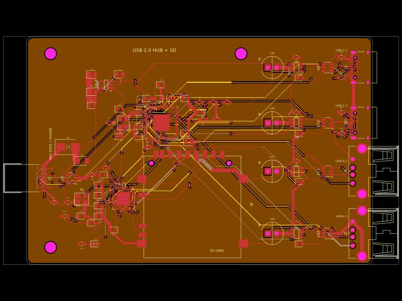
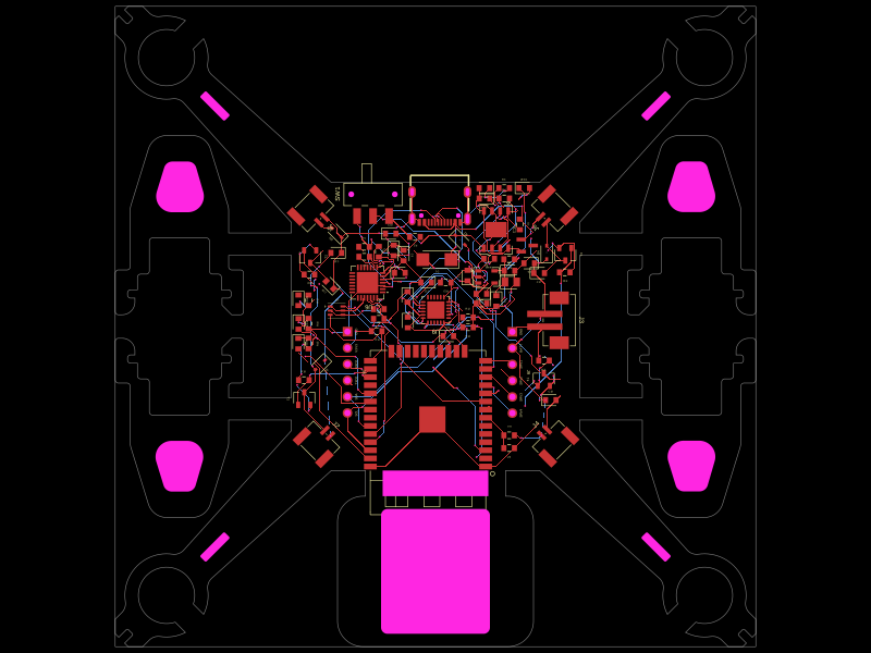
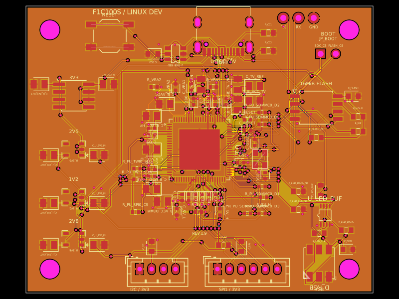
This code defines the physical layout and schematic connections for a multi-layer PCB featuring components like RTC modules (DS3231MZ), microcontroller (ATMEGA328P), LED display driver (MAX7219), and various passive and discrete components, with detailed footprints, pinouts, and placement for a clock and control interface.
# Six-Digit RTC Clock

A fabrication-reviewed four-layer tscircuit PCB for a six-digit HH:MM:SS clock.
It uses an ATmega328P-AU, DS3231 RTC, MAX7219 LED driver, AP63205 5 V buck
converter, and six FJ3191AH common-cathode displays.

The capsule outline and all front-side display, button, switch, text, and visual
0603 locations are intentionally preserved. Functional logic and power circuitry
are placed mainly on the back.

The electrical schematic is organized into four A4 sheets: power input and buck,
controller and programming, RTC/buttons/display driver, and the six display
digits. The decorative front-side 0603 links are intentionally omitted from the
schematic because they are unconnected visual footprints, not electrical parts.

## Commands

    bun install
    bun run typecheck
    bun run build

## Manufacturing release

Use the checked files in `release/` for fabrication. In particular, use
`release/clock-gerbers.zip` rather than regenerating Gerbers in an older editor
release. The checked export normalizes routed vias to through-hole vias; this is
documented in `FABRICATION.md` and `release/TSCIRCUIT_FINDINGS.md`.

Flash `clock_firmware.ino` through the six ICSP test pads. Read
`FABRICATION.md` before ordering or assembling the board.

## Status

The released Circuit JSON passes the tscircuit build and independent PCB checks
with zero reported errors. This is ready for a small prototype run, not an
untested high-volume production order. Verify supplier substitutions, assembly
rotations, and the fabricator previews before payment.