shibosoftwaredev/f1c100s-linux-nema17-stepper-controller
A four-layer NEMA 17 motor-controller PCB combining an Allwinner F1C100S Linux computer, USB‑PD/buck power system, W5500 Ethernet, STM32 real-time motion control, DRV8825 stepper driver, protection/temperature/current telemetry, USB interfaces, and local LED/buzzer diagnostics.
- Version
- 0.4.56
- License
- unset
- Stars
- 0
schematic-pages.ts
type Section = { x: number; y: number; title: string; note: string }
type Page = { number: number; title: string; subtitle: string; sections: Section[]; notes: string[] }
export const schematicPages: Record<string, Page> = {
  soc_support: { number:1,title:"Processor bypass and startup bias",subtitle:"F1C100S local supply domains and interface pull-ups; clock/reset are on 02",sections:[
    {x:-15,y:11,title:"VCC_HP / VCC_IO",note:"Common 3.3 V I/O and headphone rail"},
    {x:-15,y:6,title:"VDD_CORE",note:"1.2 V processor core"},{x:1,y:6,title:"VCC_USB / VCC_TV",note:"Internal 3.3 V domains, not host VBUS"},
    {x:-15,y:1,title:"VCC_DRAM",note:"2.5 V memory supply"},{x:7.5,y:1,title:"AVCC",note:"2.8 V analog supply"},
    {x:-15,y:-4,title:"Analog references",note:"VRA / video bypass"},
    {x:-15,y:-9,title:"Startup pull-ups",note:"Logic bias"},
  ],notes:["Rail generation and SDRAM bias: 05. These interfaces are internal, not expansion headers."]},
  linux_io:{number:2,title:"Linux boot, clock and recovery",subtitle:"Processor functional units with their associated local support circuitry",sections:[
    {x:-15,y:12,title:"24 MHz clock / reset / USB",note:"ROM FEL and Linux USB device interface"},
    {x:-4,y:12,title:"Boot storage interface",note:"Internal SPI flash, not an exposed bus"},
    {x:8,y:12,title:"Control and communication",note:"UART to STM32; SPI to Ethernet"},
    {x:-15,y:-5,title:"Manual reset",note:"Restarts Linux"},
    {x:-5,y:-11,title:"SPI NOR / recovery link",note:"Unassembled, normally bridged JP_BOOT"},
  ],notes:["DATA USB host isolation: 12. Independent motion control: 07. Rail generation: 05."]},
  soc_unused:{number:3,title:"Unused processor interfaces",subtitle:"All processor pins remain documented; unused pins are intentionally not connected",sections:[
    {x:-14,y:10,title:"RGB LCD",note:"Unused display interface"},{x:-2,y:10,title:"Audio",note:"Unused codec interface"},
    {x:8,y:10,title:"Video / touch",note:"Unused analog interfaces"},
  ],notes:["Crosses denote intentional no-connects. No large display/audio/touch expansion connectors are fitted."]},
  pd_power:{number:4,title:"USB-PD power and 5 V conversion",subtitle:"Separate POWER and DATA sockets; DATA never supplies the system rail",sections:[
    {x:-15,y:12,title:"POWER: USB-PD negotiation",note:"Default 15 V / 3 A; optional 12 V selector"},
    {x:3,y:12,title:"Input switch",note:"Voltage / gate status: 10"},
    {x:10,y:10,title:"DATA: host USB",note:"Separate 5.1 kΩ CC pulldowns"},
    {x:-15,y:-1,title:"5 V buck converter",note:"Local input/output filters and feedback network"},
  ],notes:["BUCK_IN_CAP also feeds motor protection (08). DATA VBUS is sense-only; host isolation is on 12."]},
  power_rails:{number:5,title:"Processor and logic supply rails",subtitle:"Read each regulator left to right: input capacitor → regulator → output capacitor",sections:[
    {x:-15,y:12,title:"Local voltage regulation",note:"5 V / 3.3 V feed the processor voltage domains"},
    {x:1,y:12,title:"2.5 V memory rail",note:"Regulated from 3.3 V"},
    {x:3,y:-3,title:"SDRAM reference bias",note:"Defined SVREF levels"},
    {x:-15,y:-9,title:"3.3 V distribution",note:"Fitted 0 Ω links"},
  ],notes:["3.3 V logic, 2.5 V DRAM, 2.8 V analog and 1.2 V core. Verify every rail during first bring-up."]},
  ethernet:{number:6,title:"10/100 Ethernet interface",subtitle:"Linux SPI → W5500 MAC/PHY → RJ45 magnetics; not the real-time motor timing loop",sections:[
    {x:-15,y:12,title:"SPI and W5500",note:"Interrupt/reset return to Linux"},
    {x:4,y:12,title:"Cable interface",note:"Termination and AC coupling beside magnetics"},
    {x:-15,y:-1,title:"Mode straps / references",note:"PMODE[2:0] high: automatic negotiation"},
    {x:1,y:0,title:"25 MHz clock",note:"Crystal between its load capacitors"},
    {x:-15,y:-7.5,title:"Rail distribution",note:"Fitted 0 Ω supply links"},
    {x:-15,y:-11,title:"Local bypass",note:"Associated with the W5500 supply pins"},
  ],notes:["RJ45 includes magnetics. Ethernet signal integrity and the final stackup need hardware qualification."]},
  motion:{number:7,title:"Independent real-time motion MCU",subtitle:"Linux sends UART commands; STM32 timers generate STEP/DIR without Linux scheduling jitter",sections:[
    {x:-15,y:11,title:"MCU supply and reset",note:"Local bypass and defined startup levels"},
    {x:7,y:11,title:"Hardware PD interlock",note:"PD loss blocks the driver-enable path"},
    {x:-15,y:-5,title:"Factory / recovery access",note:"SWD pads; ROM UART via Linux"},
  ],notes:["Default-disabled drive; watchdog/driver/PD/temperature faults latch a stop. Bench-test every stop path."]},
  motor_stage:{number:8,title:"Protected two-phase stepper drive",subtitle:"DRV8825 → StepperOnline 17HS13-0404S1; software-set nominal limit 0–396 mA/phase",sections:[
    {x:-15,y:12,title:"Motor power protection",note:"Fuse / blocking diode / TVS and bypass"},
    {x:-15,y:6,title:"Charge pump",note:"Bridge supply support"},
    {x:-4,y:5,title:"DRV8825 bridge",note:"STEP/DIR and enable: 07"},
    {x:8,y:4,title:"Motor cable",note:"Four-wire JST-PH; verify coil pairs"},
    {x:-15,y:-5,title:"Software current limit",note:"MCU DAC; R_ISET_210 stays DNP"},
    {x:3,y:-5,title:"Board temperature",note:"Local board heat"},
  ],notes:["R_ISEN_A/B regulate bridge current. Separate inline coil-current telemetry is on sheet 11."]},
  diagnostics:{number:9,title:"Visible status and audible alarm",subtitle:"Local annunciation is owned by STM32 and does not depend on Linux responsiveness",sections:[
    {x:-15,y:10,title:"Addressable RGB status LED",note:"MCU → AHCT level shift → series resistor → LED"},
    {x:4,y:10,title:"Magnetic buzzer",note:"MOSFET drive, gate pulldown and flyback diode"},
  ],notes:["Linux requests indications over UART; local firmware retains control of fault annunciation."]},
  power_monitor:{number:10,title:"PD voltage and gate-valid telemetry",subtitle:"Independent ADC and digital monitors; gate-valid is not downstream regulator POWER_GOOD",sections:[
    {x:-15,y:11,title:"Raw PD voltage",note:"1 MΩ / 100 kΩ divider: VBUS ÷ 11; ADC filter"},
    {x:-1,y:11,title:"Level-shifted gate status",note:"Isolates the VBUS-referenced PD gate from the MCU"},
  ],notes:["MCU PA1 measures voltage; PB3 reads PD_POWER_GOOD. Require both before arming motion."]},
  coil_current:{number:11,title:"Signed coil-current telemetry",subtitle:"Matched channels: inline Kelvin shunt → INA241 → filtered MCU ADC",sections:[
    {x:-15,y:10,title:"Coil A",note:"0.30 Ω shunt; gain 10; nominal sensitivity 3 V/A"},
    {x:-15,y:1,title:"Coil B",note:"Same topology, values and filtering as channel A"},
  ],notes:["Zero-current output is VDDA/2 (about 1.65 V). Calibrate offset/gain; samples are not calibrated RMS readings.","Telemetry does not replace the DRV8825 regulation shunts or hardware bridge protection."]},
  usb_attach:{number:12,title:"Self-powered USB host attachment",subtitle:"DATA connector → USBLC6 ESD → TS3USB31E gate → F1C100S USB; no host-to-board power path",sections:[
    {x:-15,y:11,title:"USB data protection",note:"Feed-through ESD pins preserve D+/D−"},
    {x:1,y:11,title:"Hardware data isolation",note:"Connect only while host VBUS is present"},
    {x:-15,y:0,title:"Host-VBUS detector",note:"47 kΩ base resistor and defined unplug pulldown"},
  ],notes:["OE defaults disconnected, including during ROM FEL. Qualify powered/unpowered host attachment."]},
  overview:{number:0,title:"System overview and user workflow",subtitle:"Linux networking + independent motion timing + one two-phase stepper driver",sections:[],notes:[]},
}
Related Packages
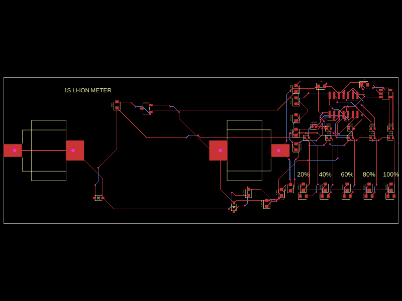 More from this authorShiboSoftwareDev/clip-on-battery-meter-2The code defines virtual representations of various electronic components—such as a BAT54WS Schottky diode and LM339 and LM393 voltage comparators—with physical pin configurations, footprints, and 3D models for PCB design.
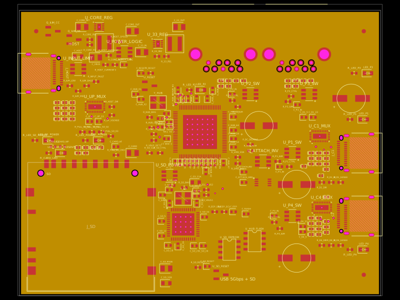 Similar packagegokul/usb3-sd-hubEngineering draft: four-layer, computer-powered USB 3 hub with one USB-C host socket, two USB-C and two USB-A accessory sockets, and a full-size SD slot. Board and three schematic previews are available. Routing and production checks are incomplete; not fabrication ready.
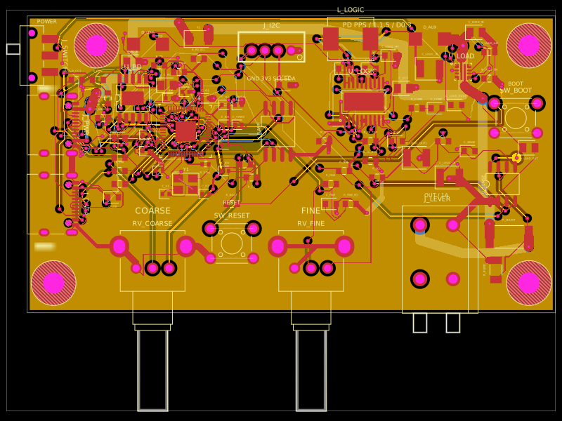 Discover something newastra/pd-power-supplyUSB-PD Power Supply with RP2040 controller