mohan-bee/mini-mp3-player
Portable, battery-powered MP3 player hardware with USB charging, microSD storage, an MCU, VS10xx audio decoder, headphone output, status controls, and regulated power rails.
- Version
- 1.2.0
- License
- unset
- Stars
- 0
mechanical/README.md
# Mini MP3 — enclosure concept

**Mounting fit** in the site shows the PCB, screws and translucent base together for checking alignment. This view is derived from the assembled circuit; it does not move the PCB or mounting features.

## Power slide switch
The switch is on the front side wall, below the lid—not a button on the lid surface. The POWER label sits near the front edge with an arrow pointing down toward the mint thumb cap. Rotate the 3D view to see the front edge; a top-down view hides the side-mounted actuator.

SW7 remains the existing SHOU HAN MSK12C02 (C431540), with its supplier CAD model. The new mint `power-slider` is a separate mechanical cap, not a replacement electrical part. It has grip grooves, a captured internal flange, and a fork around the supplier-model actuator. The cap face is 4.8 × 2.5 mm and projects about 1.45 mm beyond the front wall. The drawing specifies 1.6 ±0.1 mm full travel: [manufacturer datasheet](https://datasheet.lcsc.com/lcsc/2304140030_SHOU-HAN-MSK12C02_C431540.pdf). Verify travel, flange sliding clearance and coupling tolerance in a fit print. The 3D cap is static and does not simulate electrical switching. Open case and Mounting fit views include the slider for inspection.

## Native tscircuit assembly (current)

The actual circuit now includes **12 CAD-only subassemblies** from `PlayerAssembly.tsx`: base, accent seam, lid, insulating divider, LiPo, three-wire JST harness, four labeled button caps, LED windows, and three mounting screws. These are colored GLB meshes embedded in `models.json`, so the viewer needs no additional model hosting for these parts. The original PCB's supplier models remain in use.

Open the main site: the visible **Assembled / Open case / Exploded / PCB only** buttons all open directly in native tscircuit 3D. `index.circuit.tsx` is assembled; `exploded.circuit.tsx` separates the mechanical layers so the PCB and battery are visible. The exploded view separates the battery from its lead to reveal the assembly; the assembled view connects the lead to the battery and the mating JST plug. CAD-only objects add no PCB footprints or electrical nets.

Run `bun run models` to regenerate the GLBs and embedded model data, then `bun run build:site`. Geometry is authored in `scripts/generate-assembly.mjs` using JSCAD solids and Three.js text/GLB export. This generator is the current viewer model source; the earlier OpenSCAD file below is a separate concept draft and is not synchronized automatically.

Current native model: **88 × 68 × 21.5 mm** shell, excluding button protrusion. Battery envelope remains 52 × 36 × 5 mm; it is not shrunk to an unrealistic thickness.

The three lid holes, relieved upper spacers, PCB holes and base bosses now share H1=(-8,27), H2=(16,27), H3=(37,-26). Corner lid holes were removed. Boss tops meet PCB underside Z=-0.8; upper spacer feet meet PCB top Z=0.8. Reliefs give nearby R10/C42 pad envelopes 0.3 mm clearance. Three modeled M2 screw envelopes show the shared axes. Check actual screw lengths, printed pilot fit and spacer strength before manufacture.

The headphone bezel now has a recessed inner face at X=39.850, just 0.075 mm ahead of the supplier CAD nose. Its opening is centered on the actual jack axis Y=-14, Z=3.350, with 0.2 mm radial clearance. A larger outer pocket allows access to the recessed socket. Confirm headphone plug shoulder clearance on the physical prototype.

The PHR-3 housing now uses the [official JST PH drawing](https://www.jst-mfg.com/product/pdf/eng/ePH.pdf): 7.8 × 4.5 × 6.85 mm, with wire-entry openings and contact cavities. The SMT mating envelope is 8.6 mm above the PCB. The model aligns to the supplier header's pin row Y=-6.340943, correcting the earlier footprint-center placement. This is a dimensioned simplified housing, not the manufacturer's complete production CAD. Leads are 0.6 mm diameter with rounded bends routed around the board edge.

The two LED windows are part of the lid CAD assembly. Each has a **1.2 mm diameter × 1.5 mm stem**, flush with the outer roof, and a **2.4 mm diameter × 0.4 mm retaining flange** seated beneath the roof. Bond the flange to the lid underside; retention is not a friction-fit claim. They move and hide with the lid, including in exploded and open-case views. Light crosses the air gap from the LEDs; optical performance and adhesive compatibility require prototype testing.

Button cap faces are 9 × 6 mm with retaining flanges; stems maintain the nominal 0.2 mm switch gap. Labels remain PLAY, PREV, NEXT, VOL. All enclosure dimensions and alignments are CAD prototype values; physical fit, print tolerances and optical performance remain untested.

Use `bun run build:site` to retain the visible selector after rebuilding. A plain `tsci build --site` generates the stock viewer; `bun scripts/install-assembly-viewer.mjs` restores the selector.

## Prototype assembly limits

Use the native generator geometry above. The older enclosure.scad is an unsynchronized concept and must not be used to manufacture this revision. GLBs are colored inspection models; print tolerances, mesh preparation and physical fit are not qualified.

Install caps from inside the lid; flanges retain them and the actual tactile switches provide click and return. Verify the 0.2 mm nominal resting gap, free release and overtravel on a fit print. The power slider is modeled and must be checked against the real actuator.

Battery: protected 1S 4.2 V-full pack with cell-mounted 10 kΩ NTC, nominal body at most 52 × 36 × 5 mm before verifying cable/protection-board and swelling clearances. J2 pin 1 BAT+, pin 2 NTC, pin 3 GND. No exact pack is selected or qualified. Use an insulating divider and soft retention; keep screws and sharp edges away from the pouch.

Assembly order: battery/harness → insulating divider → PCB on bosses → connect JST → fit caps, slider and bonded windows → close lid. Check every switch releases freely, jack/USB insertion, card ejection and cable bends. Final screw length, battery fit, optical performance, thermals, drop strength and durability require prototype testing. See ../PROTOTYPE.md.
Related Packages
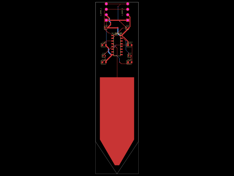 More from this authormohan-bee/soil-finalThis code defines a printed circuit board (PCB) featuring a sensor chip with associated decoupling capacitors, resistors, indicator LEDs with current-limiting resistors, pin headers for external connections, and a custom spear-shaped probe pad.
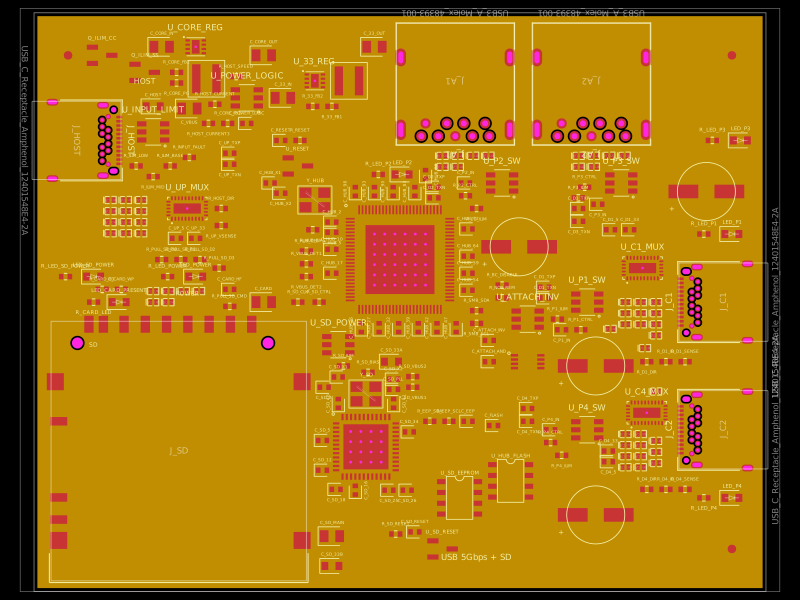 Similar packagegokul/usb3-sd-hubEngineering draft: four-layer, computer-powered USB 3 hub with one USB-C host socket, two USB-C and two USB-A accessory sockets, and a full-size SD slot. Board and three schematic previews are available. Routing and production checks are incomplete; not fabrication ready.
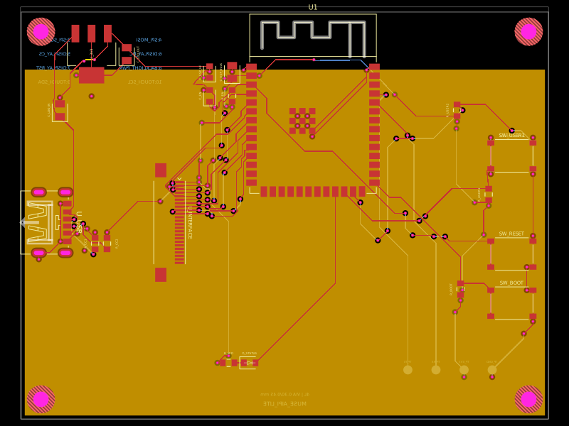 Discover something newShiboSoftwareDev/muse-aipi-lite-replacementA four-layer ESP32-S3 carrier board with USB‑C 5V input, AMS1117 3.3V regulation, FFC display/interface connector, status LED, reset/boot/user buttons, decoupling passives, test points, and ground/power planes.