imrishabh18/rp2040-motor-controller
A library of PCB component definitions covering MOSFETs, motor drivers, USB-PD control, sensors, current monitors, transistors, diodes, resistors, speakers, connectors, and mirrored bottom-side logos, with pin mappings, footprints, and 3D models.
- Version
- 1.0.55
- License
- unset
- Stars
- 5
engineering/fabrication-v1.0.48.md
# v1.0.48 fabrication review — 2026-10-23

The board passes the local geometry checks for a prototype PCB fabrication release under the settings below. It is **not ready for a complete JLCPCB assembly order**: four populated BOM parts have zero public orderable stock, and final supplier placement orientation remains to be confirmed. No powered prototype qualification has been performed for this revision.

## Fabrication settings

- Four-layer FR-4, 1.6 mm finished thickness; 1 oz outer / 0.5 oz inner copper. The 0.10 mm tracks are incompatible with simply changing this to a 2 oz order without another clearance review.
- Approximately 42.30 × 42.32 mm routed outline. Use the supplied Edge_Cuts, not a rectangular or V-scored outline. Check actual motor screw, shaft, magnet and enclosure fit before ordering.
- ENIG and green solder mask are recommended for the fine-pitch parts. Keep the supplied mask, paste and plated/nonplated drill files distinct. Ask the assembler to provide suitable tooling rails/panelization.
- All 303 vias are plated through all four layers; smallest design hole is 0.30 mm. No blind/buried drilling is needed. Twelve approximately 0.30/0.50 mm imported thermal vias lie inside the DRV8825 exposed pad. Their top is open within the thermal-pad mask and their bottom is tented. Bottom tenting is not a filled-and-capped via process; confirm the exposed-pad soldering process with the assembler to control solder loss/voiding. Filled/capped processing is an available assembly improvement, not specified by these files.
- Use `assembly-bom.csv` and `assembly-pick-and-place.csv`. They contain 107 populated top-side components and no bottom-side assembly. U_ENCODER is DNP on the bottom; C_ENCODER and C_ENCODER_BULK are DNP on top. Bare mounting features and removed test points are excluded from assembly.

The design limits were checked against [JLCPCB's current capabilities](https://jlcpcb.com/capabilities/pcb-capabilities): conservative 0.10 mm track/space, 0.15 mm different-net pad spacing, 0.20 mm via drill spacing and inner-via-to-copper distance, 0.30 mm inner plated-pad drill clearance, and 0.20 mm routed-edge clearance. The explicit board rules and exact results are included in the reports.

## Checks completed before publication

Fresh exports pass the drill, NPTH/edge clearance and connector-slot checks. The delivered Gerbers contain all four copper layers, solder mask, paste, outline and separate plated/nonplated drill files. All twelve thermal-via drills, the exposed top thermal pad, bottom tenting and solid ground contact on inner/bottom copper are verified from the exports.

Native routing DRC and independent copper/physical-connectivity checks report no errors, shorts, disconnected nets or audited clearance violations. Ground copper forms one connected network. Four Kelvin sense branches remain separated from their load-current paths. The updated toolchain passes all 34 circuit tests, typechecking and schematic style analysis. PCB placement DRC has zero errors and warnings; the placement heuristic retains twelve orientation/escape suggestions for already-routed components. Three existing PCB angle advisories are also retained. These are not represented as a warning-free design: the built JSON still has 302 metadata, supplier-lookup and trace-width/style warnings. Motor-current path checks separately bound the short narrow escapes and nominal resistance; hardware temperature rise is unmeasured.

All PCB component, pad, hole, trace, via, paste and copper-pour records match the pre-update v1.0.47 local build exactly. This release updates tooling and evidence without changing physical copper. The v1.0.47 cloud checker failure (`relate(shape1, shape2).covered`) was a runtime exception, not an identified copper violation. The new cloud build is verified separately after upload; local success alone does not establish cloud success.

## Assembly blockers and required order review

Public JLCPCB stock checked on 2026-10-23 (one board, before batch minimums/attrition):

| Designator | Actual BOM part | JLCPCB code | Public orderable stock |
|---|---|---|---:|
| Q_PD_ENABLE | BSS84-7-F | [C85202](https://jlcpcb.com/partdetail/C85202) | 0 |
| U_PD | CH224K | [C970725](https://jlcpcb.com/partdetail/C970725) | 0 |
| U2 | W25Q16JVUXIQ | [C2843335](https://jlcpcb.com/partdetail/C2843335) | 0 |
| U3 | AP2112K-3.3TRG1 | [C23380830](https://jlcpcb.com/partdetail/C23380830) | 0 |

The other 46 unique populated part codes have sufficient reported public orderable stock for one board; stock is not reserved. Preorder/consigned stock or separately verified compatible replacements are needed for the four shortages. Do not substitute a different CH224 variant or a different flash package without checking pinout, configuration and firmware compatibility.

The exporter cannot automatically verify the supplier pin-1 orientation for D_PWR, J_USB, J_MOTOR_USB, C_MOTOR_BULK and U_PD_PG. Their exported rotations are retained, not guessed. Check these against the assembler's actual placement preview, along with every polarized/IC part, before approving assembly. The existing Q_BUZZER and Q_PD_ENABLE placement corrections are retained.

## Prototype acceptance

This is a design/DFM review, not manufacturer CAM approval or production qualification. Bring-up still needs measured 3.3 V rails, USB programming, PD negotiation/fallback and PG behavior, 9–20 V motor operation, current calibration, thermal rise, hot-plug/regeneration peaks and mechanical fit. Default 5 V PD is below the DRV8825 operating range. Application firmware must control voltage transitions, motor enable and temperature/fault handling; no device firmware is included. Keep the nominal approximately 1 A peak winding-current target until the actual PCB, motor, cable, supply and enclosure are qualified.
Related Packages
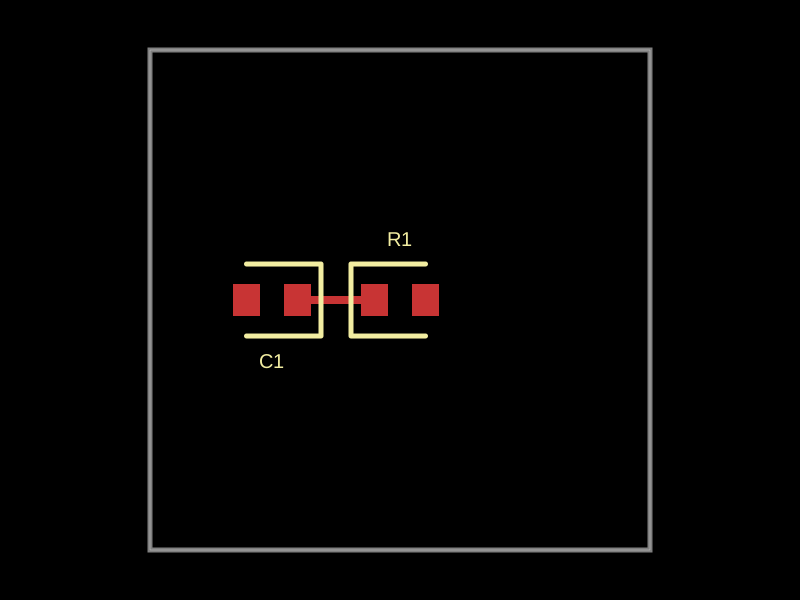 More from this authorimrishabh18/TESTA 10mm square electronic board with a 1kΩ resistor and a 1000pF capacitor connected between the resistor's first pin.
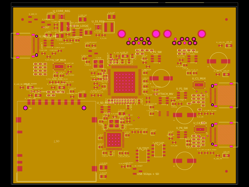 Similar packagegokul/usb3-sd-hubEngineering draft: four-layer, computer-powered USB 3 hub with one USB-C host socket, two USB-C and two USB-A accessory sockets, and a full-size SD slot. Board and three schematic previews are available. Routing and production checks are incomplete; not fabrication ready.
 Discover something newtscircuit/standard-jst-programmer26 × 42 mm USB-C RP2040 programmer with JST and TC2030 IDC SWD, NRST, selectable sensed 5 V / 3.3 V power, RGB status, and importable JST SH/Tag-Connect targets. Top-side assembly.