hrithik18k/punck-tscircuit-recreation
A four-layer Eurorack drum/sampler controller PCB built around an STM32H743, dual QSPI flash, PCM5100 stereo DAC, TL074 analog audio circuitry, input clamps, 12V-to-3.3V power regulation, MIDI/USB/SWD connectors, controls, LEDs, and trigger/audio I/O.
- Version
- 1.0.3
- License
- unset
- Stars
- 0
NATIVE_BUILD.md
# Native schematic and autorouted PCB

This supersedes the earlier PCB-only import for active development.

## Source

- `native/components.circuit.tsx`: electronics board, 113 electrical components (the original decorative four-layer marker is not an electrical schematic component).
- `native/controls.circuit.tsx`: controls board, 36 electrical components.
- `native/NativeBoard.tsx`: native resistors/capacitors, generic pin-labelled chip symbols for other devices, schematic sections, and netlabels that create native electrical traces.
- `native/ExactFootprint.tsx`: native pad, plated-hole, non-plated-hole and silkscreen primitives reconstructed from the source geometry.
- `native/components.json`, `controls.json`: editable component, footprint and connectivity definitions. These contain **no PCB traces, vias, or copper pours**.
- `native/layout-overrides.json`: checked-in schematic layout adjustments used by `scripts/generate-native.ts`.

The native schematic is a newly laid-out, labelled-net representation, not a reproduction of the KiCad symbol artwork. Generic chip boxes represent ICs, connectors, transistors, test points, and combined illuminated switches. Resistors and capacitors use native symbols. Source design values and pin identities remain in the data. Unconnected source pins remain unconnected.

## Autorouting

The board enables the local tscircuit autorouter. Existing KiCad routing is not supplied as input. Debug logs and SimpleRouteJson under `evidence/router-*` record `previous_traces=0`. This is a new PCB route, not a rendering of imported tracks.

Run:

```powershell
cd E:\project\tscircuit\Punck
bun run build:native
bun run verify:native
bun run dev:native
```

The controls and electronics boards have different electrical circuits. The passive mechanical front panel has no electrical schematic to autoroute; its original/reference import remains under `prepared/panel.circuit.json`.

## Deliberate differences and workarounds

- C24, R16, C26 and C23 are rotated 180 degrees on the PCB following the placement check; subsequent copper is autorouted anew.
- U7 pin 2 and RESET1's repeated pads use separate native physical pin aliases on the same original nets. Their original pin IDs are retained in data. This avoids core dropping PCB ports for repeated pad hints.
- JP1's overlapping circle/rectangle pad pieces are unioned into one polygon per logical pad. Circle contours use 128 segments, with under 0.0002 mm maximum radial approximation error.
- No source copper pours are carried into the native board. Ground and power connections are routed traces. Plane design, return paths, high-speed constraints, current capacity, and production component selection still require engineering review.
- The default shorts test checks outer-layer Gerber copper. It is not a complete four-layer fabrication DRC or signal-integrity validation.

## Evidence

`evidence/native-verification.json` compares original pin/net assignments with the native output, verifies shared schematic/PCB identities, and lists remaining build errors. The `native-*placement*`, `native-*shorts*`, and `native-*components*.log` files contain validation and autorouting results. Review the latest files rather than intermediate failed attempts.

The earlier `README.md` and issue-report sections describe the imported reference workflow. Original KiCad sources and PCB-only imports remain available for comparison.

## Final validation (7 October 2026)

| Native board | Schematic/PCB components | Routed trace records | Vias | Pin/net mismatches | Output errors |
|---|---:|---:|---:|---:|---:|
| Electronics | 113 / 113 | 302 | 217 | 0 | 0 |
| Controls | 36 / 36 | 114 | 76 | 0 | 0 |

Both outputs pass schematic placement, PCB placement (no placement issues), and outer-layer Gerber shorts checks. Electronics also passes `runAllChecks` after the repair below. Warnings remain for missing courtyard geometry and incomplete electrical pin-role metadata; CLI adds inferred connector accessibility warnings because insertion directions are unspecified. Component supplier/MPN selection is incomplete. These warnings and the omitted source planes prevent treating this as fabrication-ready.

### Required post-route repair

The electronics autorouter still produces two via-in-pad errors with `allowViaInPad:false` and 0.4 mm clearance. `scripts/repair-native-vias.ts` moves two vias and their coincident trace vertices, then recomputes all checks before writing the output. It preserves the raw router output and records exact moves in `evidence/native-via-repairs.json`. Unexpected errors or failed checks stop the build. The controls board needs no manual route repair and uses 0.2 mm clearance.

`bun run build:native` includes this repair step. Running `tsci build native/components.circuit.tsx` directly shows the upstream errors; the corrected deliverable is `preview/components.circuit.json`. No imported KiCad tracks are used. This is **tscircuit autorouting followed by two explicit via repairs**, not an entirely untouched autorouter result.

## Browser-native routing fix

`index.circuit.tsx` now uses `native/punck-router.browser.js`, bundled from the readable `native/punck-router.ts`. It runs tscircuit capacity autorouter 0.0.958, moves the two known via coordinates and coincident route vertices before emitting the routing result, and lets core generate vias and run its normal DRC. It does not remove error records or enable via-in-pad. This makes the correction available in the website evaluator without a separate filesystem script. If a changed layout produces different errors, core still reports them.

## Multiple schematic sheets
The electronics entrypoint assigns every component and netlabel to one of ten named schematic sheets. Cross-sheet connections retain their original board-level named nets; no PCB placement or net assignment is changed.
Related Packages
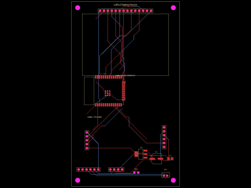 More from this authorhrithik18k/Chatting-DeviceThis code defines React components representing surface-mount voltage regulator and resistor chips with specified pin layouts, footprints, and 3D CAD models for electronic hardware design.
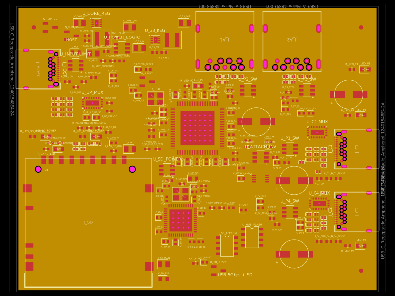 Similar packagegokul/usb3-sd-hubEngineering draft: four-layer, computer-powered USB 3 hub with one USB-C host socket, two USB-C and two USB-A accessory sockets, and a full-size SD slot. Board and three schematic previews are available. Routing and production checks are incomplete; not fabrication ready.
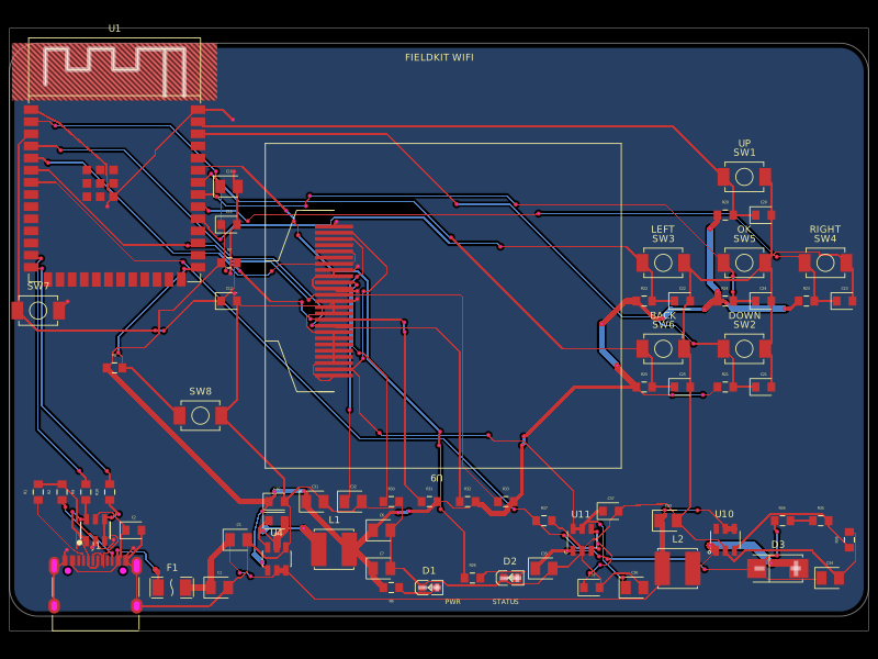 Discover something newgokul/fieldkit-usbUSB-C-powered ESP32-S3 Wi-Fi/Bluetooth handheld with an SMD 128x32 OLED, six navigation buttons, USB-C power/data, complete checked routing, and four native schematic sheets.