abse/smartwatch-v1-pcb
Routed bare ESP32-S3 smartwatch with SDR PSRAM, touch AMOLED, Qi receiver and compact/exploded 39 × 50.5 × 14.5 mm provisional assembly.
- Version
- 0.2.0
- License
- unset
- Stars
- 0
mechanical/ASSEMBLY_STATUS.md
# Mechanical fit status

The native `assembly.circuit.tsx` uses 19 `assembly.subassembly` elements with embedded GLB models. All model vertices use the CAD Z-up frame with baked world transforms and separate mesh instances. Native CAD rotations are zero: the GLB importer supplies its default Y/Z remap. The native exporter’s common (-X, Z, Y) frame is normalized for comparison. Each of the 19 subassemblies is checked individually, rather than checking only overall scene bounds. Its local build emits 19 `cad_component` records; the generated parts are not hidden with `doNotPlace`.

The CAD study uses a 39 × 50.5 × 14.5 mm smooth body, the actual routed 34 × 38 × 0.8 mm PCB, centered maximum 36.85 × 44.66 × 2.31 mm touch AMOLED, and maximum protected battery envelope inside the PCB. The active area is 30.91 × 38.17 mm. Glass covers 83.6% of the face; active pixels cover 59.9%. The earlier 46 mm body length is not achieved.

The routed PCB, battery/adhesive/insulation, wireless receiver/ferrite/insulation, motor/neck/factory adhesive/pedestal, battery and coil thermistors, soldered lead paths, display connector/latch, button actuator, PPG baffle and rear window are represented. The two motor lead paths are 12.48 and 11.33 mm, within its factory 12 ±2 mm length. Battery factory leads are deliberately shortened and individually insulated extensions added. The motor driver is on the main PCB; the motor is mounted inside the case.

The body height includes the glass and rear cover. The study allocates at least 1 mm expansion space below the maximum battery, even above the thin coil temperature sensor. The maximum coil envelope is 15.5 mm diameter × 0.85 mm, with ferrite toward the battery. It does not overlap the PPG opening. Supplier drawing-based envelopes and visual details are identified as such; they are not manufacturer-supplied solid models.

## Unresolved display flex

The manufacturer's published CFAL368448A0-0193DW PDF is internally labelled 0139DW. It gives a 50 mm flex, 19 contacts at 0.3 mm pitch, maximum 0.23 mm flex thickness, minimum 1.5 mm bend radius and 2 mm straight setback, but does not dimension populated/rigid zones or all width-transition and X datums. The back photograph shows chips and passives on the broad flex. The present fold preserves 50 mm length and minimum radius, but passes through unknown populated zones. Those bends are not qualified. The flex controller/passive protrusions cannot be placed faithfully without the missing dimensions; a smooth ribbon is only an envelope study.

Request from the supplier: a STEP or dimensioned factory-folded assembly for the exact 0193DW revision; component positions/heights and permitted fold zones; flex attachment and contact-tip datums relative to the glass; whether the 2.11 ±0.20 mm depth includes folded flex/components; recommended mating insertion depth and contact-side orientation. Do not bend through an IC or rigid stiffener. This information determines whether the 14.5 mm stack and a shorter body can be verified.

The raw mesh contact report keeps adhesive bonds, solder attachments and motor/thermistor lead exits visible. Contacts are not silently excluded. There are no remaining reported wire penetrations into unrelated modeled parts, but the absent flex-component geometry prevents a complete assembly clearance pass.

Prototype qualification is separate: antenna detuning by display metal, PPG standoff/light seals, coil tuning/FOD, wire strain relief, charger faults, battery swelling/current limits, thermal rise and measured runtime. No physical prototype tests have passed in this cloud task.

## Model completeness and rear corners

The PCB has 142 top and 12 bottom footprints. All 142 fitted bodies are represented: 140 native component bodies plus the drawing-based Hirose J1 housing and Sunltech L1 power inductor. The remaining 12 footprints are exposed solder terminals or test pads, shown in the PCB copper. L1 uses supplier maxima 2.2 × 1.8 × 1.0 mm (SLO201610T Rev.01). The importer ignores node matrices and can collapse shared mesh transforms; baking every instance preserves the actual placements on both faces.

The cavity corner radii follow the tapered rear shell. A 1,217-section audit detects no unintended corner cut-throughs. The rear floor is 0.4 mm; the minimum uncut wall at the front glass lip is about 0.148 mm and is not structurally qualified. There are no added external bottom fins. The black internal optical well isolates the PPG light path. Underside and bottom-populated-PCB snapshots are included for inspection.

Large planar rear faces retain flat normals while the continuous rolled side skin is shaded smoothly. Only horizontal cap normals are split, preventing seams between tangent side strips. The revised profile has a gently convex side rather than a long straight box wall, retaining the same maximum body dimensions and cavity containment.

## Native preview display

The pinned native GLB converter drops embedded image textures. The heart-rate demo is therefore exported as colored planar spans of the same image, so the actual native 3D preview retains the interface. This visualization lies 0.001 mm above the glass to avoid z-fighting and is excluded from the physical 14.5 mm stack. It is not sensor telemetry.

## Supplier appearance and Apple styling reference

The case uses Apple Watch SE 2 as a reference for smooth rolled edges, taper toward glass/rear, a dark satin finish and a flush pill-shaped actuator. It is a proposed custom polymer case with our dimensions, not an Apple enclosure or Apple internal assembly. No nonfunctional crown is added. The side actuator retains the actual SW1 position.

The battery's silver foil, yellow protection tape and printed PKCELL LP552530 / 3.7V 350mAh identification follow Adafruit's product photograph. Its visual shoulders and protection band stay within the maximum 25.5 × 32.5 × 5.7 mm envelope. The stainless motor can, off-white glue and red/blue leads follow Vybronics' photograph. The coil uses the drawing's 0.17 mm wire diameter and maximum 15.5 × 0.85 mm envelope, with dark ferrite toward the battery. Its winding count/lay and pouch creases are visual approximations. Factory coil leads are 25 ±2 mm, so the assembly explicitly trims them to 20 mm and uses separate insulated extensions with individual splice sleeves; it does not claim a factory harness spans the entire route.

Source RGB values are converted to linear glTF PBR factors, including the preserved native OBJ-derived component materials. This makes glass, molding and OLED backgrounds dark rather than pale CAD grey. PCB textures and every supplier model's geometry/material assignment remain intact. Photos establish approximate appearance, not measured factory color specifications. The enclosure has no purchased color standard yet. See [appearance-evidence.json](appearance-evidence.json) for exact source URLs and reconstruction limits. Missing populated display-flex dimensions still prevent an identical, fully qualified physical assembly.
Related Packages
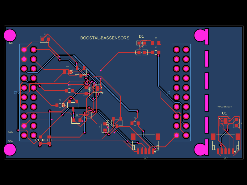 More from this authorabse/boostxl-bassensorsThis code defines React components for various electronic hardware components such as LEDs and sensors, specifying their 3D models, footprints with SMT pads, silkscreen outlines, and pin labels for PCB integration.
 Similar package0hmX/pcbgolf-modular-checkpointA partial 3D assembly of seven separate PCBs—five USB carriers, an MCU board, and an SBU board—with modeled USB/DC connectors, but no routing, wiring, supports, or tilted-board mounting.
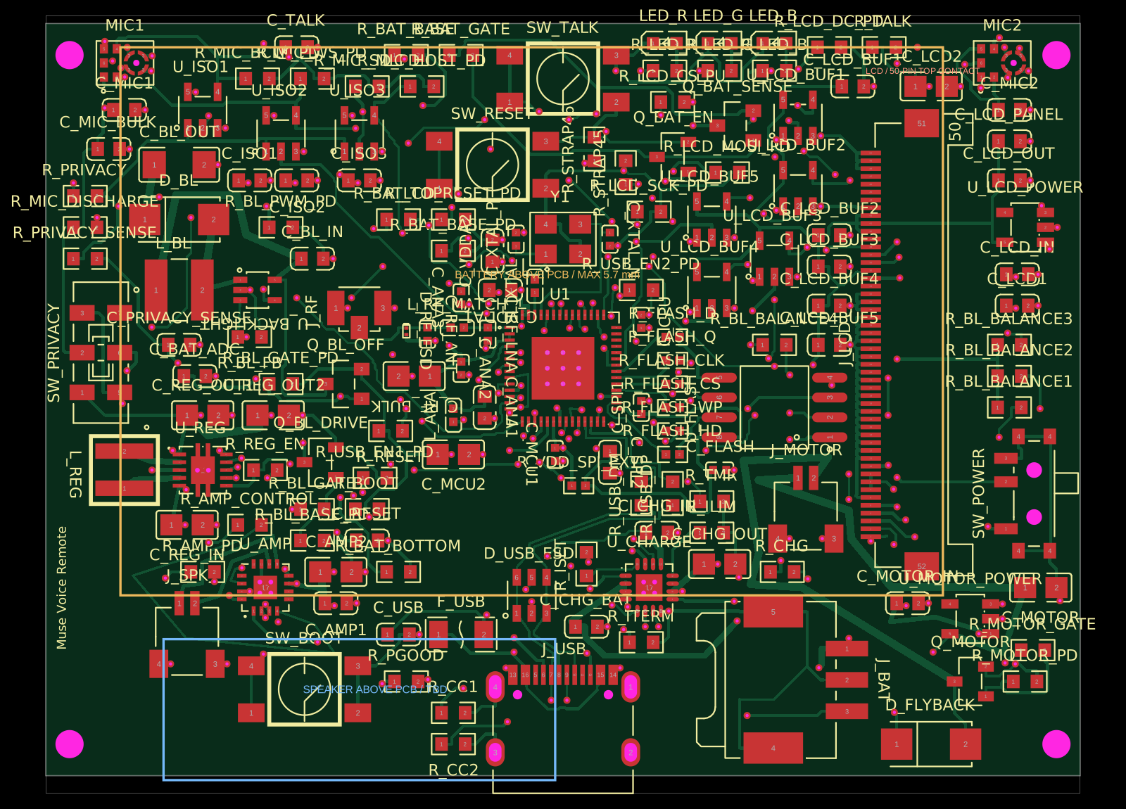 Discover something newAnasSarkiz/muse-voice-remoteMuse Voice Remote v1.3.0: checked prototype PCB/PCBA handoff. Bare ESP32-S3R8 chip, 155 TOP parts from 56 stocked JLCPCB imports with supplier CAD retained. Exact ER-TFT028A2-4 no-touch LCD, dual microphones, TALK, physical privacy, Wi-Fi, speaker, haptic and USB-C. Includes circuit.json, Gerbers/drills, JLC BOM/CPL, segmented stencil artwork and 19 filled/capped thermal-hole map. Native/factory DRC clean; 20 tests pass. See manufacturing/FABRICATION-NOTES.md for stackup and assembly requirements. Physical device/enclosure/RF qualification, firmware and connected-service MUSE integration remain unverified.