README.md
# Three-panel flex smartwatch — v0.2.20

Version **0.2.20** clears the last native trace-style warning by simplifying one OLED_CLK bottom-layer route. All six native entry points build with **zero warnings, zero DRC errors and zero build errors**. All 94 nets / 500 functional pads remain connected. All 623 vias retain **0.30 mm holes and 0.45 mm pads**. Component placement, board shape, bends, stiffeners, enclosure, mounting, cables and electrical pin assignments are unchanged.

The separate `tsci check pcb-style` command reports **65 staircase advisories**, down from 67; it has no odd-angle findings and still exits 1 for those advisories. No checks or warning thresholds are suppressed. Four fresh bottom-layer PCB/Gerber scans report zero shorts, and twelve prior scans remain valid after exact comparison of all unchanged non-bottom copper, vias, pads and connectivity. See [current validation](reports/validation-report.json), [OLED clock fix](reports/oled-clock-style/result.json), [before/after](reports/oled-clock-style/before-after.png) and [publication provenance](publication-provenance.json). Earlier reports below are historical baselines.

## Published v0.2.16 baseline

This revision corrects the reviewed regulator headroom, low-rail cutoff/recovery, charge termination, I2C pull-ups, RF/Qi bypass and ESP32 exposed-pad cooling. The current routed design has 94 nets, 500 functional pads and 162 flat-top components. The original project remains untouched. See [electrical corrections and order qualification](reports/electrical-fixes/review.html) and [validation](reports/validation-report.json).

The published v0.2.16 `tsci check pcb-style` measurement was 74 advisory findings: 5 odd-angle and 69 staircase findings. These are reported separately from native DRC and shorts. The earlier v0.2.15 style cleanup (153 to35 findings) is historical; this electrical revision adds and reroutes copper. Do not treat style findings as a manufacturing approval.

Prototype procurement remains on hold pending the listed supplier drawings, approved flex/filled-via fabrication process and electrical/mechanical bench evidence. The selected Adafruit4237 / PKcellLP552530350mAh battery and JST-ACH harness arrangement are retained. The 1A regulator does not increase the selected pack's525mA continuous discharge rating.

## Display-up 3D viewer

Open [the complete watch with the display facing upward](https://abse--smartwatch-flex-top-only-v0-2-15.tscircuit.app/display-up.html). This viewer applies one rigid 180-degree rotation to the entire exported PCB and mechanical assembly. All original mesh buffers and relative positions are preserved. The native tscircuit PCB and 3D viewer remain available and retain the exact routed circuit. The display-up transform is a presentation-only operation; see `preview/display-up/rotation-verification.json`.

Fork: https://tscircuit.com/abse/smartwatch-flex-top-only. The original https://tscircuit.com/abse/smartwatch-v1-pcb is untouched.

The main `watch.circuit.tsx` is now one native `assembly.device` containing the actual routed `<board>` and its two bends, together with the enclosure, display, mounting parts and connector-only cables. This uses the [clip-lamp assembly pattern](https://tscircuit.com/muse/book-reading-clip-lamp#3d). The fork's PCB and 3D tabs both use this circuit: PCB shows its developed layout; 3D applies both native folds and places the enclosure around it. If the PCB tab reports unsupported WebGPU geometry, click to interact and right-click **Rendering Engine → Canvas**. The PCB is not an imported model. Case/bezel/display translucency is a viewing aid; render `Watch` with `transparentShell={false}` for opaque parts. The [assembly site](https://abse--smartwatch-flex-top-only-v0-2-15.tscircuit.app) defaults to the same circuit; select **3D**. `assembly.circuit.tsx` removes the bezel and display for screw installation. `pcb.circuit.tsx` remains an optional display-only flat view without flex annotations; use `index.tsx`/`flat.circuit.tsx` for fabrication.

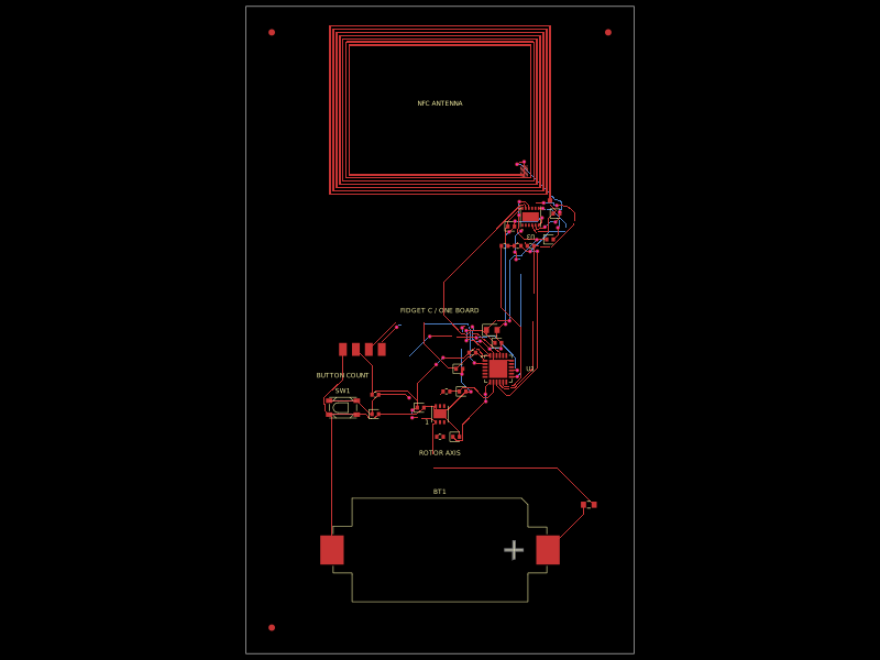
The flat PCB is 35.4 × 135.2 × 0.2 mm, with four copper layers and all 162 components mounted on its top face. Three panels join through two parallel −180° bends with 3.9 mm neutral radius. Both use `bendSide="left"`, which the native folded renderer supports. The frame and sensor/coil paddle face the wrist after folding; the display faces upward. The 24 mm paddle has 0.2 mm nominal clearance from the frame opening on each side. Every crossing trace is perpendicular to its bend, with no components, drills or stiffeners in the bend bands.

Open `watch.circuit.tsx` or `assembly.circuit.tsx` for the complete upright assembly, including the AMOLED display, battery, motor, low-profile plugs and swept insulated wiring, sensor windows, black optical seal, side button and screw-retained PCB cradle. `index.tsx` is the live folded manufacturing circuit; `flat.circuit.tsx` is its developed layout; `enclosure-fit.circuit.tsx` retains the native manufacturing circuit within a mechanical fit reference. The assembly includes the native manufacturing circuit directly. Mechanical parts use a shared rigid case-to-PCB transform matching the enclosure-fit study; their physical positions in the enclosure are unchanged. The AMOLED body renders with a clean screen-off glass surface; nonphysical demonstration artwork is omitted to prevent coplanar flicker. Its physical vertices and faces are unchanged.

The frozen route has physical copper connectivity across all 94 nets and 500 required functional pads, zero orphan copper, zero native DRC errors and zero PCB/Gerber shorts. Reports record the actual native circuits, route cache and check fingerprints. The approved electrical revision adds rail supervision, regulator headroom, RF/Qi bypass, charge termination and exposed-pad thermal vias. Unlisted components, connections and placements remain unchanged; see the source-integrity audit and electrical review. Four bare peripheral interfaces are replaced with stocked JST ACH headers; their eight mechanical mounting lands are NC.

The complete **modeled** exterior is **39 × 50.5 × 14.5 mm maximum**, including the display and flush side button. The outside case dimensions are preserved; its obsolete sensor/button apertures are filled and new aligned apertures cut. The motor shelf is trimmed to leave 0.15 mm side clearance from the ferrite. Nominal FCL checks cover populated PCB, battery/ferrite maximum envelopes, motor, thermal probes, case, display, mounts, plugs and wires. These dimensions do not constitute a physical production tolerance guarantee.

## Connector-only assembly

J3 battery, J4 motor drive, J7 battery NTC and J8 coil NTC use **JST BM02B-ACHSS-GAN-ETF(LF)(SN), JLCPCB C5118738**. The manufacturer's nominal mated header/housing envelope is **4.2 × 4.3 × 1.4 mm**. Use ACHR-02V-S housings with SACH-003G-P0.2B contacts and compatible AWG32 insulation; the modeled long harness OD is 0.38 mm. The haptic harness mates with a PicoBlade inline pair; the existing motor's 12 ±2 mm AWG32 leads are trimmed and crimped, with no solder splice. Its reserved mated envelope is 4.45 × 9.4 × 3.5 mm, held in a captive cradle pocket. The display uses its existing Hirose FH35C-19S-0.3SHW(50) FPC connector, JLCPCB C2889269. See `mechanical/CONNECTOR_ASSEMBLY.md` and sourcing reports for exact contact parts.

All five harnesses use the native **`assembly.cable` host** through the project-local `components/AssemblyCable.tsx` CAD adapter. Stock core currently models SH/PH cables and cannot render a routed ACH watch harness. The adapter emits explicitly dimensioned ACH/PicoBlade cable GLBs as CAD components, checks endpoint identities and changes only cable CAD rendering. No core package, PCB check or electrical net is modified. This is project-provided ACH support, not a claim of stock native ACH model support.

No cable is hand-soldered to the PCB or spliced during watch assembly. Battery and temperature probes require matching factory prewired, crimp-terminated harnesses; their drawings and supplied tolerances must be approved before procurement. The printed receiver coil is PCB-integrated and needs no cable. Service/test copper uses a removable spring-contact fixture. Semiconductor/connector soldering during PCB manufacture is separate from cable assembly.

## Optical integration and PCB mounting

The ZSPD4003LG sensor has a self-contained opaque GLB preserving the supplier model's vertices/material colors and 7 × 3.5 × 0.91 mm nominal envelope. Two skin-facing windows align with its LED and photodiode fields. A 0.55 mm opaque septum and compressed black perimeter/divider seal separate the light paths. Forty triangle-intersection rays pass unobstructed; this proves geometric clearance, not optical performance or waterproofing. Inserts are individually bonded, 0.2 mm thick and flush with the rear surface.

A removable cradle supports the main 0.4 mm FR4 backing and captures the 0.65 mm stiffened PCB stack with two integrated rear retention roofs and two removable front arms. Two purchased M1.6 × 6 mm countersunk screws secure the front arms and cradle. The flat PCB needs no mounting holes. The front case-integrated posts are 3.0 mm diameter with 1.3 mm blind pilots; clearance bores are 1.9 mm. Rear posts are solid 2.0 mm locators. Cradle rails, ribs, retention arms and connector-pocket walls are 1.2 mm thick. A post-clearance sweep checks 81 insertion positions. Printable case body and top bezel, cradle, two front arms, button and optical inserts are separate watertight solids; optical inserts require verified optical material/finish. Test the three mounting coupons before a full print. Fit the stiffened panel under the rear roofs before completing the folds, connect the crimped harnesses outside the case, lower the PCB/cradle into the open case body, install the front arms/screws, then fit the top bezel and display. Hole finishing, thread strength, print fit and handling need prototype verification.

## Qualification before tooling

The supplier display drawing does **not** provide its populated-flex thickness or factory-fold geometry. The modeled body and connector fit, but the physical 14.5 mm assembly limit cannot be guaranteed until that flex and the complete tolerance stack are verified. Gasket compression, optically transparent insert materials, adhesives, crimp tooling, battery swelling limits, flex materials/R3.9 static bends, antenna performance, wireless charging, mount strength and real skin signal require hardware qualification. Stock connector availability is a checked snapshot, not a procurement reservation.

Documentation: [tscircuit PCB bends](https://docs.tscircuit.com/elements/pcbbend), [optomechanical heart-rate integration](https://www.analog.com/en/resources/technical-articles/guidelines-for-the-optomechanical-integration-of-heartrate-monitors-in-wearable-wrist-devices.html). See `reports/validation-report.json` for the final measured and electrical results.

## PCB cradle

Thicker 1.2mm cradle and motor-connector pocket features, two integrated rear PCB retention roofs, and two accessible M1.6 countersunk front screws replace the four miniature tapped mounts. Main-backing locating gaps are 0.25mm at the sides and 0.3mm at the ends, with a 0.2mm rear roof gap. The battery-temperature harness follows a lower passage to clear the stronger supports. The nominal exterior remains 39 × 50.5 × 14.5mm. See `mechanical/PCB_MOUNT.md` and the three `mount-fit-*.stl` samples before printing; printer fit and thread strength need physical verification.

Cloud CI runs the original pinned-lockfile install and all six circuit builds through `scripts/cloud-run.mjs`. Full diagnostics are kept in downloadable `cloud-install.log` and `cloud-build.log` artifacts; the console receives progress and the real CLI result.

Site thumbnails use actual PCB/CAD snapshots in `mechanical/site-previews`, generated with `scripts/generate-site-previews.mjs`. This avoids a timeout in the CLI's automatic thumbnail renderer for the enclosure model. After all six normal builds, the runner compares each freshly compiled PCB and CAD geometry against the snapshot manifest and fails on any difference. Interactive 3D viewers still use the freshly compiled circuit JSON. Native DRC and build checks remain enabled.

## Main assembly hardware integration v0.2.10

The closed `watch.circuit.tsx` preview now uses the real case-body/post union and a separate top bezel, both as native `assembly.printedpart` elements. The cradle and each front arm are also separate printed parts; each purchased ISO7046 M1.6 × 6 PH0 screw is a named `assembly.part` with a detailed nominal thread/drive model. Stock standard screw models start at M3 and do not fit this watch. No imaginary assembly.screw element or scaled M3 hardware is used.

The original one-piece upper rim blocks screw and driver insertion. `assembly.circuit.tsx` now shows the real installation stage with bezel/display removed: install the PCB/cradle into the open case body, then both screws from above, then the bezel/display closure. The 0.1mm reserved bezel bondline preserves the original 39 × 50.5 × 14.5mm nominal exterior; adhesive, alignment and waterproofing need prototype qualification. The blind pilots are 3.8mm deep, require at least 3.1mm finished bottoming-tap thread, and leave 0.9mm beneath the screw tip. See `reports/mount-installation.json` and `mechanical/PCB_MOUNT.md`. Print the two case parts separately; the combined mounted-enclosure STL is an assembly reference.

The fixed motor shelf is removed from the case because it trapped J3/J8 during installation. Its 0.2mm maximum insulating support stack now travels with the removable PCB/motor module on the existing FR4 stiffener. Specify a thin FR4/insulating shim and compatible bonding material within that total thickness; do not print a 0.2mm load-bearing shelf. Thickness, bonding and vibration retention require prototype verification. The actual open-body sweep includes the PCB, cradle, motor support, motor and inline connector.

Large validation snapshots are transported as `.json.gz` to avoid cloud sandbox file-transfer timeouts. The snapshots remain available for optional audits; the cloud build uses the current circuit source. For standalone audit scripts, first run `bun scripts/expand-validation-snapshots.mjs`.