abse/rp2350-mcu-board
This code defines a compact, four-layer PCB hardware layout for the Raspberry Pi RP2350A microcontroller module, including the main IC, power regulation, USB-C connector, STM32-compatible headers, and associated passive components, with detailed component footprints, net connections, and copper pour zones for powering and ground references.
- Version
- 0.0.11
- License
- unset
- Stars
- 0
RP2350_FOUR_LAYER_VERIFICATION_2026-09-04.md
# Local four-layer RP2350 verification

**Historical whole-board-pour checkpoint.** The current local board uses a smaller top VBUS pour; see [the copper-pour update](RP2350_COPPER_POUR_UPDATE_2026-09-04.md) for current results and hashes. The figures below describe the preceding checkpoint.

Verified 2026-09-04 on the complete `index.circuit.tsx` board. **Routing target met locally. Not an assembly/fabrication release.** No publication, ordering or autorouter implementation changes were made. Published project version 0.0.7 remains the six-layer source.

## Result

| Check | Published six-layer source, local verification | Local four-layer result |
| --- | ---: | ---: |
| Copper layers | 6 | 4 |
| Generated DRC errors | 0 | **0** |
| All-layer Gerber shorts | 0 | **0** |
| Physically connected required nets | 58/58 | **58/58** |
| Opens / shorted net groups / unresolved pads | 0 / 0 / 0 | **0 / 0 / 0** |
| Crystal signal vias | 0 | **0** |
| Longest crystal signal path, 10 mm limit | 9.489175 mm | **9.489175 mm** |
| Unique via drills | 127 | 123 |
| Generated warnings | 55 | 56 |

Typecheck, explicit complete-board build/render, netlist and placement commands completed successfully. Published routing, continuity, board-edge and via-in-pad checks produce no errors. The separate physical drill audit finds no via-hole spacing or drill-to-unrelated-track violations. The final board has 51 components, 178 source traces, 183 PCB traces and 125 via records representing 123 unique drills.

All 28 constrained two-port paths and all 18 geometrically checked fanouts to their same-net planes pass. The 0.12 mm and 0.3 mm connectivity checks pass for 37/37 and 3/3 required nets respectively. Original values, JLCPCB selections, source-net memberships, specified widths, via limits and crystal-length limits are preserved. No components, including the crystal and edge connectors, moved relative to the six-layer layout.

## Changes

- Changed the complete board from six layers to four.
- Kept GND on inner1 and moved the 1.1 V core-supply pour and fanout target from inner4 to inner2.
- Moved the 3.3 V pour to bottom and VBUS pour to top. Both outer pours are covered with solder mask.
- Kept the established routing phases and fanout directions.

All PCB routes, vias and pour boundaries are generated by the published solvers. There are no source `pcbPath`/manual PCB traces, manually placed vias, manual pour outlines, route-cache inputs, dependency overrides, patches or routing-algorithm changes. Published `tscircuit@0.0.2462` was rechecked as latest for this run.

Three trials were evaluated. Simply deleting the VBUS pour gave zero DRC errors and shorts but failed the required-width connectivity audit, so it was rejected. Moving the whole VBUS net into the wide routing phase introduced three DRC errors and one confirmed short, so it was also rejected. Restoring the existing phases and adding the generated top VBUS pour passed the checks above.

## Remaining warnings and limitations

There are **56 generated warnings**, not zero warnings: 25 missing courtyards, 14 supplier-footprint similarity warnings, 14 pin/power/ground specification warnings and three stored-route length warnings. A separately invoked published width checker retains 11 net-wide warnings for mixed-width supply/ground nets. None of these warnings was hidden or disabled.

The native length checker counts the complete stored fanout, including copper after its first connection to the plane. Its warnings and the strict full-route audit failures remain recorded. A supplemental check flood-fills actual same-net pour and physical via geometry, without trusting inside-pour flags:

| Connection | Limit | Full stored route | First verified plane contact |
| --- | ---: | ---: | ---: |
| U1_DVDD1, C11 supply feed | 5.5 mm | 5.840064 mm | 4.878777 mm |
| U1_DVDD2, C10 supply feed | 5.5 mm | 5.852454 mm | 4.058387 mm |
| C_LDO_OUT_G | 2.5 mm | 2.548627 mm | 2.454096 mm |

The board contains 87 BREP pour regions: one GND on inner1, one V1V1 on inner2, three V3V3 on bottom and 82 VBUS regions on top. The required endpoints are connected; this does not assert that every small copper island is tied to its intended net or that every pour neck is adequately sized. Pour-island cleanup, neck/spoke current capacity, return-path/signal integrity and manufacturer DFM still need review. Width checks exclude undersized trace routes but do not erode copper pours to certify minimum neck widths.

Physical connectivity was checked at 100 pixels/mm, with eleven checker controls passing. Plane-contact geometry was checked at 500 pixels/mm with five controls passing; length conservatively includes 1.6 mm per via, as in the native checker. Finite-resolution checks do not guarantee fabricated hardware behavior.

The preserved GPIO supplier selections remain an assembly blocker: 1×22 footprints versus 2×11 parts C492428/C2894972. Proposed replacement C22465881 still requires approval. No parts were substituted. Do not order assembly from the current BOM. The pre-existing review Gerber ZIP belongs to the six-layer version, not this local trial.

## Files and evidence

- [Current full-board PCB snapshot](dist/index/pcb.png)
- [Current PCB SVG](dist/index/pcb.svg)
- [Current circuit JSON](dist/index/circuit.json)
- [Archived four-layer output](/Users/abdolsalamallawlabi/Documents/Codex/2026-08-27/work-on-the-complete-rp2350-mcu-2/board-four-layer-20260904/03-top-vbus-output/circuit.json)
- [Six-layer source backup](/Users/abdolsalamallawlabi/Documents/Codex/2026-08-27/work-on-the-complete-rp2350-mcu-2/board-four-layer-20260904/six-layer-source/index.circuit.tsx)
- [Six-layer output backup](/Users/abdolsalamallawlabi/Documents/Codex/2026-08-27/work-on-the-complete-rp2350-mcu-2/board-four-layer-20260904/six-layer-output/circuit.json)
- [Physical connectivity](/Users/abdolsalamallawlabi/Documents/Codex/2026-08-27/work-on-the-complete-rp2350-mcu-2/board-four-layer-20260904/03-top-vbus-connectivity.json)
- [Source/constraint audit](/Users/abdolsalamallawlabi/Documents/Codex/2026-08-27/work-on-the-complete-rp2350-mcu-2/board-four-layer-20260904/03-top-vbus-audit.json)
- [Plane-contact audit](/Users/abdolsalamallawlabi/Documents/Codex/2026-08-27/work-on-the-complete-rp2350-mcu-2/board-four-layer-20260904/03-top-vbus-plane-contact.json)
- [Published checks](/Users/abdolsalamallawlabi/Documents/Codex/2026-08-27/work-on-the-complete-rp2350-mcu-2/board-four-layer-20260904/03-top-vbus-published-checks.json)

The same evidence directory contains build, typecheck, netlist, placement, Gerber shorts, width and drill logs/reports, plus rejected trial checkpoints.

## SHA-256

```text
index.circuit.tsx
1d01fed0083d7fdde53332993eca706229bfa4f1579acf1d7c83f21e6d0e34a4
RP2350A_Essential_KiCad_Reference.circuit.tsx
b8a8160823786226d777cb368892ba005b593e4db916850ae380b8810f42684d
dist/index/circuit.json
56cf1afbf3920b4bb4ae4efb096ab882851b668d8fd4f62453f589fa88f91f39
dist/index/pcb.png
3a87303962e37e7f1cde01082bf7bc258049b21587eb3bada400bbb7dd2b427f
```
Related Packages
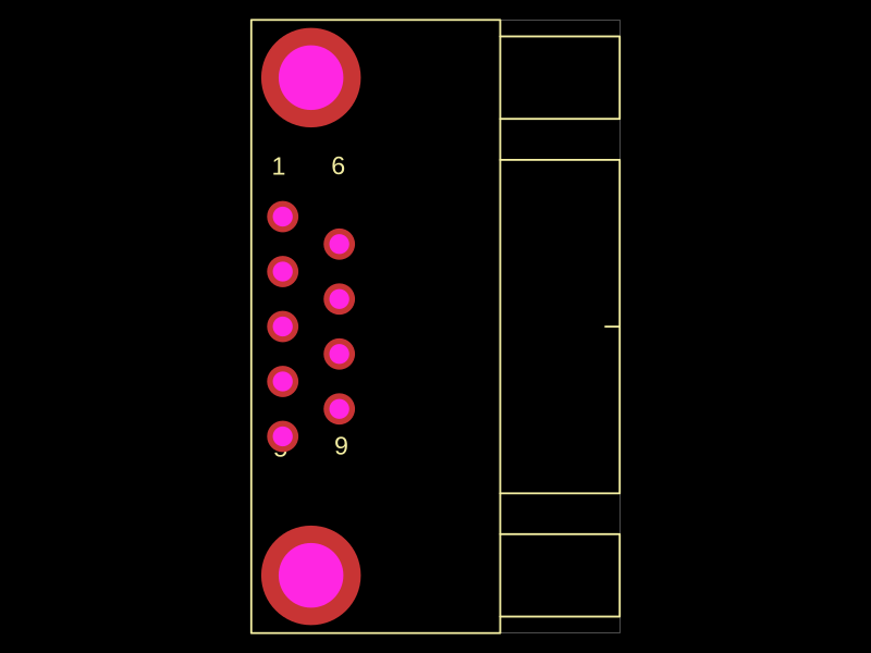 More from this authorabse/C75749Generated from JLCPCB part number C75749
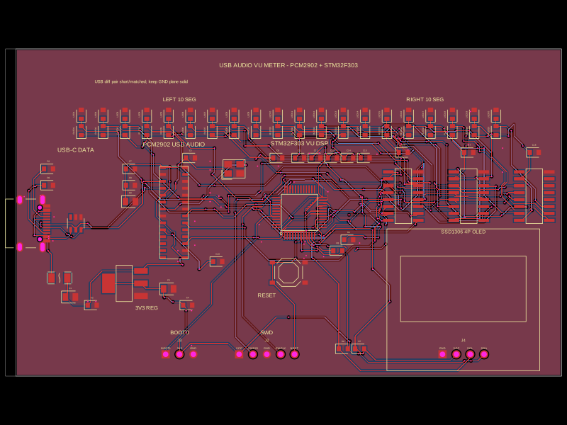 Similar packageimrishabh18/STM32F746G-DISCOThis code defines the hardware layout of a USB audio vu-meter circuit, including key components such as voltage regulators, microcontroller (STM32F303CCT6), audio codec (PCM2902), USB-Ethernet isolator, power regulation, reset switches, and associated passive components, with their physical footprints, pin configurations, and routing for PCB design.
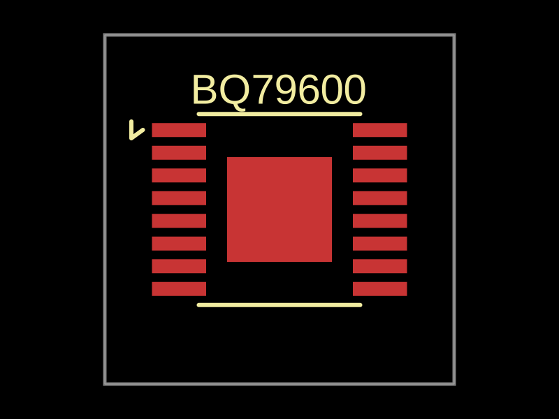 Discover something newbeaver/bq79600A 10mm x 10mm PCB with a BQ79600 battery monitor IC featuring 8 pins for power, discharge control, threshold detection, trigger, output, control, and reset.