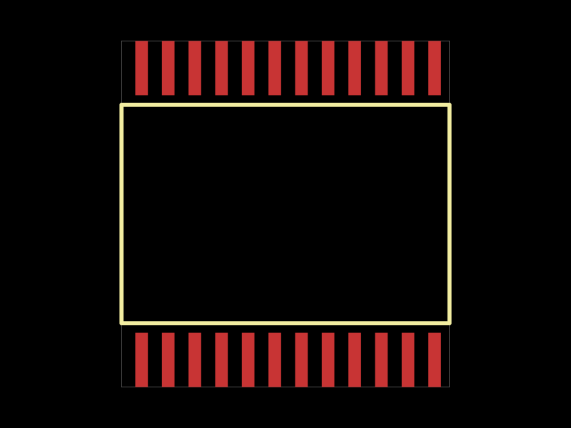
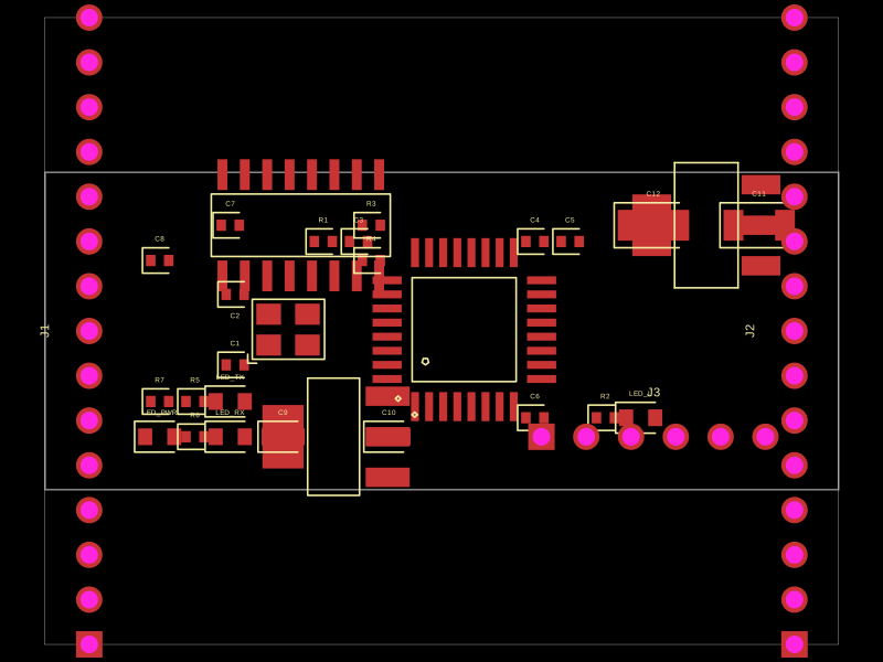
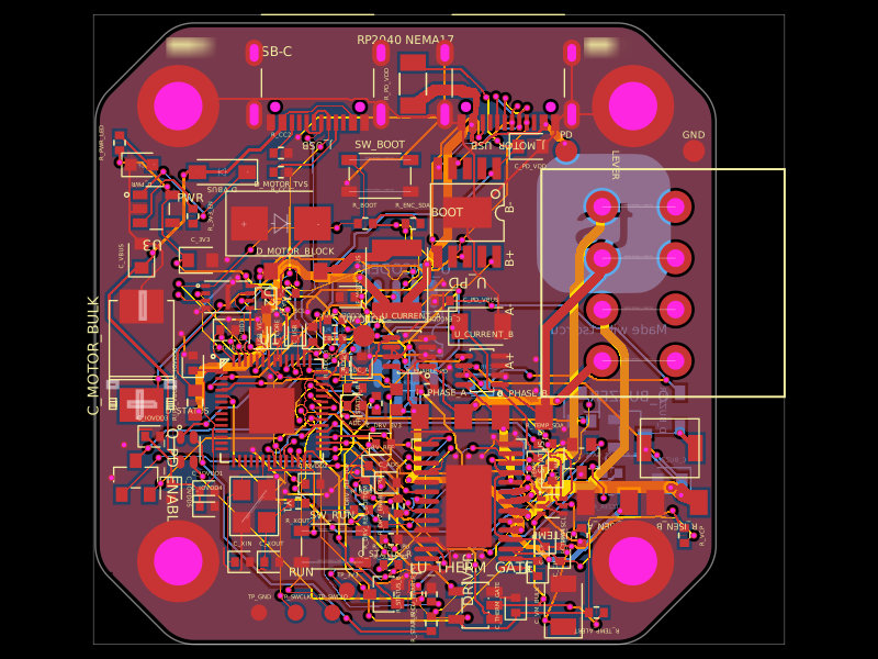
This code defines the hardware layout of a USB audio vu-meter circuit, including key components such as voltage regulators, microcontroller (STM32F303CCT6), audio codec (PCM2902), USB-Ethernet isolator, power regulation, reset switches, and associated passive components, with their physical footprints, pin configurations, and routing for PCB design.
# USB Audio VU Meter

USB Audio VU Meter is a 2-layer tscircuit PCB for a USB sound-card endpoint that drives a 20-segment stereo LED bar graph and exposes an optional SSD1306-style OLED header.

## Hardware

- PCM2902 USB audio codec for USB audio enumeration.
- STM32F303 microcontroller for meter DSP, peak hold, fast attack, and slow decay firmware.
- USB-C power/data input with CC pull-downs, fuse, and USB ESD protection.
- AMS1117-3.3 3.3 V regulator.
- Three SN74HC595 shift registers driving 10 left-channel LEDs and 10 right-channel LEDs.
- Optional SSD1306-style 4-pin OLED module header with a silkscreened module outline.
- SWD header, reset switch, and BOOT0 service header.

## Layout Intent

- Board size: 100 mm x 60 mm, 2 layers.
- USB-C is placed on the left board edge.
- PCM2902 is near USB to keep D+ and D- short and length matched.
- STM32F303 is beside the codec.
- LED bar spans the top edge.
- OLED module area is reserved on the lower-right side; J4 is the solderable 4-pin footprint and the silkscreen marks the module/glass outline.
- SWD and BOOT0 access are on the bottom edge.
- J2, J3, and J4 use through-hole pin-header footprints for assembled or hand-soldered headers.
- LED colors are arranged as a center-out stereo meter: green near the middle, yellow next, red at the outside ends.

## Commands

```bash
bun install
bunx tsc --noEmit
bun run build
bun run dev
tsci build
tsci dev
```

## Manufacturing Notes

The project uses JLCPCB/LCSC supplier part numbers in `src/parts/jlcpcb.ts` where practical. Pin headers are marked DNP because OLED and debug headers are commonly hand-soldered during bring-up.

Before fabrication, verify the exact PCM2902 package variant and USB-C footprint against vendor datasheets, inspect generated Gerbers, and tune USB differential impedance for the chosen PCB stackup.