abse/rp2350-mcu-board
This code defines a compact, four-layer PCB hardware layout for the Raspberry Pi RP2350A microcontroller module, including the main IC, power regulation, USB-C connector, STM32-compatible headers, and associated passive components, with detailed component footprints, net connections, and copper pour zones for powering and ground references.
- Version
- 0.0.11
- License
- unset
- Stars
- 0
LOCAL_ELECTRICAL_FIX_STATUS.md
# Local electrical corrections — narrow review checkpoint

2026-09-04, narrow trial 23, complete `index.circuit.tsx`. **Not fabrication-ready. Do not order these outputs.**

## Dependency and mechanical change

Updated the actual board project from published `tscircuit@0.0.2462` to **0.0.2463**, verified against the npm latest endpoint on 2026-09-04. Both package.json and bun.lock were updated. Installed dependencies include @tscircuit/core 0.0.1837, @tscircuit/cli 0.1.2021 and capacity-autorouter 0.0.866. No local tarballs, patches or overrides were installed.

Reduced width **48 → 44 mm (8.3%)**; height remains 64 mm, with four layers and a 0.8 mm target thickness. GPIO headers are at x = ±19 mm. USB, STEMMA QT and SPI remain at the board ends. Pinouts, component values, supplier selections, crystal placement and original explicitly requested widths are preserved.

The RP2350 essentials module is an ordinary placement group, not a separately autorouted subcircuit. The retained design uses one automatic routing pass and only an inner1 GND pour. No manual PCB paths, PCB route hints, manually placed routing vias, saved routes or generated-output edits are used.

## Fresh verification

| Verification | Latest-package baseline, 48 mm | Retained checkpoint, 44 mm |
| --- | --- | --- |
| Typecheck | Pass | Pass |
| Complete build/render | Completed with errors | Completed with errors |
| Native routing errors | 5 | 4 |
| All-layer Gerber-mode short check, 100 pixels/mm | 1 short on inner2 | 0 shorts |
| Independent physical connectivity, 100 pixels/mm | 59 nets, 0 opens, 1 shorted-net group | 59 nets, 0 opens, 0 shorted-net groups |
| Unresolved pads | 0 | 0 |
| Drill-to-unrelated-track checks | 3 failing comparisons involving 2 vias | 0 failures |
| Crystal | Five zero-via signal paths | Five zero-via signal paths; longest 9.442872 mm, limit 10 mm |
| Ground pour | Floating fragments present | One connected region; 0 floating or unsampled regions |
| Required 0.3 mm power connectivity | VBUS fails | GND, V3V3 and VBUS fail |

The power-width result is a **regression**, not hidden by the lower native error count. This checkpoint is retained as a narrower, short-free review baseline, not as an electrically qualified improvement or production release.

There are 53 components, 175 PCB traces, 132 via records representing 129 unique physical drill locations, and two NPTH locating holes. Native warnings total 59: 27 missing courtyards, 14 supplier/footprint warnings, 16 route-length warnings and two reference-designator warnings. The separate published width checker reports 13 additional width warnings.

The wrapper scripts returning exit 0 do not certify zero findings: the published routing-check array contains four errors plus 16 length warnings. The build CLI itself also exits 0 despite its four errors.

## Remaining routing and electrical blockers

| Blocker | Exact result |
| --- | --- |
| GPIO26 / GPIO27 clearance | 0.040 mm gap near (-4.7361, -0.8163), below the 0.100 mm requirement |
| Via-limit reports | U1_VREG_PGND: 2; U1_VREG_FB: 4; VREG_LX: 2; each constrained to 0 |
| Actual LX routing | 8.906953 mm planar length, two vias, top and bottom layers; not acceptable as the intended compact same-layer switching loop |
| Actual feedback path | C7 positive to U1 FB: 7.418001 mm, zero vias; exceeds the inferred 5.5 mm local limit |
| Other overlength local paths | C11_V1V1, C13_V3V3, C14_V3V3, RGB_BUF_GND and RGB_BUF_OE |
| Power routing | Required 0.3 mm connections are not physically connected through sufficient-width copper on GND, V3V3 and VBUS |
| Copper beneath switching node | The inductor-body keepout clears the sampled body area, but 13 of 57 samples under the routed top-layer LX segments still have inner1 pour beneath them |
| Ground-return topology | Quiet AVDD filter ground still joins switching-capacitor ground in the autogenerated tree; separate returns are not established |
| Assembly | Previously excluded 1×22 footprint / 2×11 header BOM mismatch remains unchanged; no permission response to change it was received |

The native via checker counts all PCB branches assigned to a source trace. For example, the direct C6-to-PGND path has zero vias, but another same-net branch assigned to U1_VREG_PGND has two. The direct C7-to-FB path also has zero vias while other branches contribute four. These reporting limitations do **not** excuse the real two-via LX route, long feedback path, undesired feedback branching or power-width failures.

The routing input dumped by the current published core does not carry the source maxViaCount/maxLength constraints. Same-net nominal widths are present, but the resulting copper still contains undersized sections. These are observations from this board and installed toolchain, not proof that no valid placement exists.

## Trials and retained changes

Manufacturer-reference review guided the compact C6/C7/L1 and AVDD-filter placement, feedback connection to C7, and inner1 inductor-area keepout. BOOTSEL/pull-up placement was adjusted for the narrower outline, C12 was moved away from the USB escape corridor, and the RGB buffer capacitor was repositioned. The original crystal placement is unchanged. A logical 0.3 mm RGB supply-distribution connection was added; it has no PCB coordinates or saved route.

Additional trials prioritised local circuits, wide power routing, and separate automatic ground fanouts. They were rejected when they introduced shorts, opens, crystal-via violations or routing failures. Trial 21 stopped with Pipeline 9's error: “cannot reconnect preloaded trace fanout:C6_GND:source-0 for exact repair.” Trial 22 completed but had 16 native errors, a shorted-net group, floating ground fragments and crystal-via violations.

Trial 23 freshly reproduced the short-free geometry of trial 16 after removing an ineffective phase selector. It did not reuse cached routes. No experimental dependency or router changes were kept.

## Export verification

A separate verification environment uses the unmodified published **circuit-json-to-gerber@0.0.104**. On this exact circuit JSON it emits four copper layers, one plated L1–L4 drill file and a separate NPTH file. All **129 unique physical vias are drilled exactly once**, with zero coordinate/diameter/count mismatches; both NPTH holes are present.

This verifies drill fidelity and copper-layer count only, not fabrication readiness, full copper fidelity, impedance, thermal performance, assembly data or manufacturer DFM. The board's bundled CLI export is not silently replaced with this separate exporter. Diagnostic exports are labelled DO_NOT_ORDER. No KiCad fix or other upstream patch was installed into this project.

The deferred header BOM issue, stencil/CPL review, exact manufacturing stack-up, supported load/current budget, signal/power integrity and hardware bring-up qualification remain outside any zero-short claim. See [power and assembly requirements](POWER_AND_ASSEMBLY_REQUIREMENTS.md).

## Evidence and reproducibility

Evidence directory: [narrow-board-20260904](</Users/abdolsalamallawlabi/Documents/Codex/2026-08-27/work-on-the-complete-rp2350-mcu-2/narrow-board-20260904>).

- [Fresh summary](</Users/abdolsalamallawlabi/Documents/Codex/2026-08-27/work-on-the-complete-rp2350-mcu-2/narrow-board-20260904/23-narrow-checkpoint-summary.json>)
- [Source snapshot](</Users/abdolsalamallawlabi/Documents/Codex/2026-08-27/work-on-the-complete-rp2350-mcu-2/narrow-board-20260904/23-narrow-checkpoint-source/index.circuit.tsx>)
- [Full-board PCB snapshot](</Users/abdolsalamallawlabi/Documents/Codex/2026-08-27/work-on-the-complete-rp2350-mcu-2/narrow-board-20260904/23-narrow-checkpoint-output/pcb.png>)
- [Physical connectivity and pour audit](</Users/abdolsalamallawlabi/Documents/Codex/2026-08-27/work-on-the-complete-rp2350-mcu-2/narrow-board-20260904/23-narrow-checkpoint-connectivity.json>)
- [Power-width audit](</Users/abdolsalamallawlabi/Documents/Codex/2026-08-27/work-on-the-complete-rp2350-mcu-2/narrow-board-20260904/23-narrow-checkpoint-power-width.json>)
- [Constraint/path audit](</Users/abdolsalamallawlabi/Documents/Codex/2026-08-27/work-on-the-complete-rp2350-mcu-2/narrow-board-20260904/23-narrow-checkpoint-constraints.json>)
- [Electrical audit](</Users/abdolsalamallawlabi/Documents/Codex/2026-08-27/work-on-the-complete-rp2350-mcu-2/narrow-board-20260904/23-narrow-checkpoint-electrical-audit.json>)
- [Drill clearance audit](</Users/abdolsalamallawlabi/Documents/Codex/2026-08-27/work-on-the-complete-rp2350-mcu-2/narrow-board-20260904/23-narrow-checkpoint-drill-clearance.json>)
- [Diagnostic Gerber verification](</Users/abdolsalamallawlabi/Documents/Codex/2026-08-27/work-on-the-complete-rp2350-mcu-2/narrow-board-20260904/23-gerber-diagnostic/verification.json>)

The constraint comparison's strict width/via-set equality fields are false because new explicit widths and stricter regulator limits were added. Its edge-placement equality is false because the headers intentionally moved inward. Original requested widths and via limits are preserved; values/parts and source-net membership compare unchanged. Missing fanout-specific audit entries are not a claim of open nets: this retained design uses ordinary routing, not the fanout solver.

SHA-256:

```text
index.circuit.tsx
e037ada5303ff2e6ef5515b5565df77daefdbeccca0d0c1301d2033cc42f23e0
RP2350A_Essential_KiCad_Reference.circuit.tsx
26c85d7b25b573502993051e8f5b78d49b30bf32339062f6755ccad2dba35ff2
package.json
12a4d3610f7b326bbbe1751ec6510e988fdf767a35de8061cc5c5d8b804bdc15
bun.lock
b874ac41f985898b91925a4160c79831a39c93774fc2589be43c3f8b9af8886d
dist/index/circuit.json
aebac2c5e499d9d2a4c284b7160bf88141b6d712a56358a79e0e572330d6cc03
```

Finite-resolution copper checks and conservative path-length checks do not replace manufacturer DFM or physical qualification. No project push, manufacturing submission or order was performed.
Related Packages
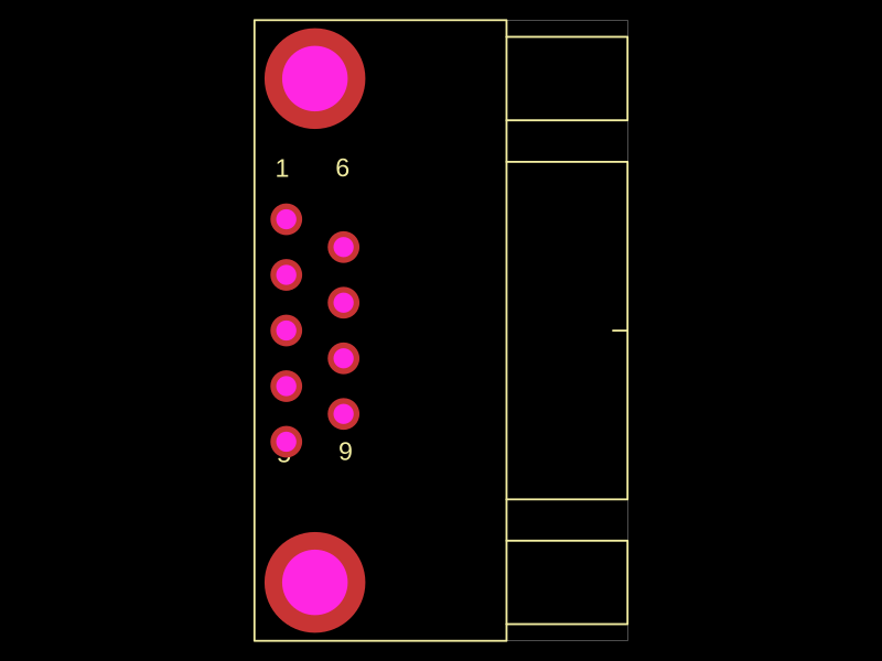 More from this authorabse/C75749Generated from JLCPCB part number C75749
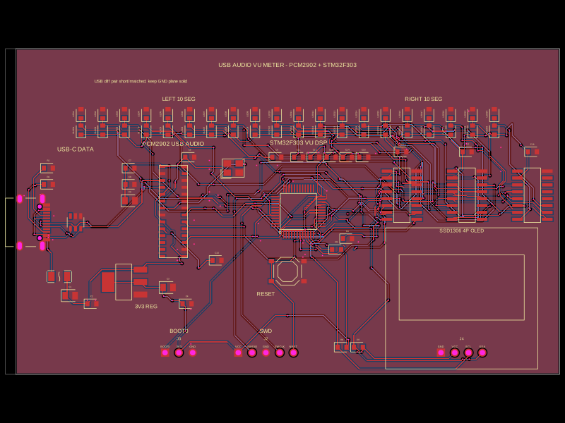 Similar packageimrishabh18/STM32F746G-DISCOThis code defines the hardware layout of a USB audio vu-meter circuit, including key components such as voltage regulators, microcontroller (STM32F303CCT6), audio codec (PCM2902), USB-Ethernet isolator, power regulation, reset switches, and associated passive components, with their physical footprints, pin configurations, and routing for PCB design.
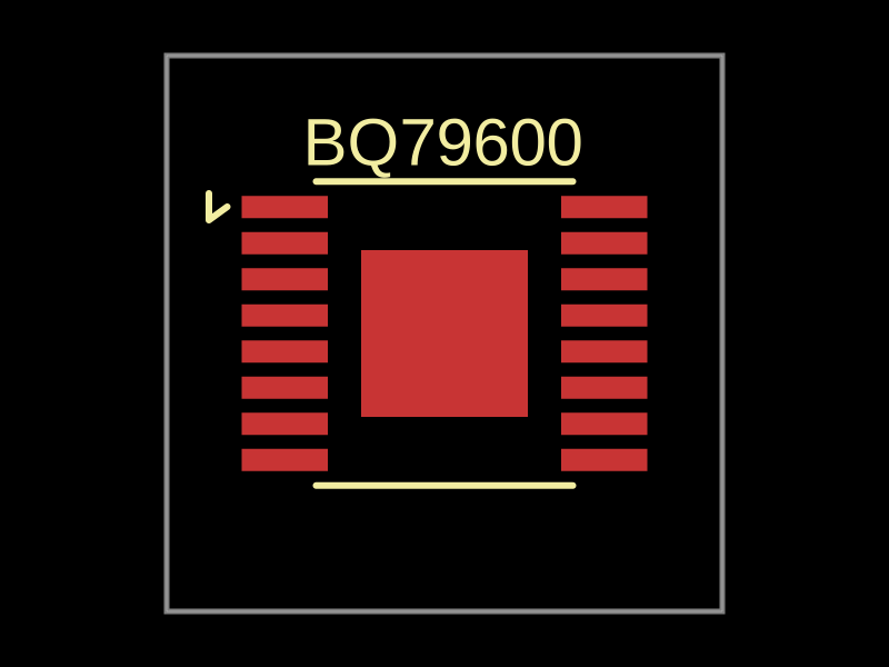 Discover something newbeaver/bq79600A 10mm x 10mm PCB with a BQ79600 battery monitor IC featuring 8 pins for power, discharge control, threshold detection, trigger, output, control, and reset.