abse/dual-usb-peltier-assembly
A USB‑C PD Peltier controller PCB combining RP2040 control, adjustable buck‑boost TEC power, temperature sensing, fan regulation, USB programming, protection, status LEDs, and external accessory hardware.
- Version
- 0.4.6
- License
- unset
- Stars
- 0
firmware/README.md
# RP2040 USB control and firmware

The board has **PD IN** for Peltier power and **PROGRAM** for configuration and firmware updates. PROGRAM can power the logic by itself; it cannot energize the Peltier without qualified PD power. There is no screen or button UI.

The application uses the **official Raspberry Pi Pico SDK 2.2.0** and its pinned **TinyUSB 0.18.0** submodule, running only on RP2040 core 0. A 12 MHz crystal supplies the SDK's system/USB clocks. External flash is **Winbond W25Q128JVSIQ, 16 MiB**; SDK `boot2_w25q080` uses the compatible Winbond quad command set. The PCB remains unrouted: USB enumeration, actual flash programming, and converter operation await bench validation.

## Configure once, then use PD alone

```sh
python3 -m venv .venv
.venv/bin/pip install -r host/requirements.txt
.venv/bin/python host/control.py configure 12.0 5.5
```

This sends STOP → SET → SAVE, storing the nominal **12 V / 5.5 A** TEC1-12706 profile. A later PD connection starts the saved profile after approximately one second of stable qualified input. Add `--run` to start now when PD is already connected. Unplugging PROGRAM leaves an operating output running on PD.

```sh
.venv/bin/python host/control.py configure 12.0 5.5 --run
.venv/bin/python host/control.py status
.venv/bin/python host/control.py stop
.venv/bin/python host/control.py run
```

The host tool selects a single connected driver and checks its STATUS response before sending control commands. Use `--port /dev/cu.usbmodem…` or `--port COM…` before the command when needed. Any serial terminal also works with newline-terminated commands; CDC does not depend on the selected baud rate.

| Command | Behavior |
|---|---|
| `SET 12000 5500` | Set millivolts and milliamperes atomically, only while OFF |
| `SAVE` | Save the current profile only while OFF; acknowledge only after flash readback |
| `RUN` | Start after full PD, limit, and register checks |
| `STOP` | Stop and cancel pending automatic start for this PD connection |
| `STATUS` | JSON run/CC/PD/fault, limits, approximate readings, saved-profile validity, `boot_ready`, and HOT/COLD probe telemetry |
| `CLEAR` | Stay OFF and clear the protective fault latch |
| `BOOT` | Disable output, then enter the built-in RP2040 USB BOOTSEL loader |

Limits are **2.1–15 V in 0.1 V steps**, **0.50–6.00 A in 0.05 A steps**, and **72 W maximum nominal**. Invalid inputs, integer overflow, unsupported steps, and excessive power are rejected without changing settings. The default is 12 V / 5.5 A, **OFF until a valid profile has been saved or RUN is requested**.

A source interruption shorter than one second stops output and requires RUN. After PD has been absent for at least one second, a new qualified connection can start the saved profile. SC/OVP, ADC, converter communication, and excessive measured-limit faults latch OFF; they cannot automatically retry. CLEAR stays OFF, while an explicit RUN retries all checks and clears the latch only after success. The protective latch survives application watchdog/reboot resets in scratch register 2. A power/RUN hardware reset may clear the retained register and is an intentional new power session.

POWER indicates logic supply, RUN indicates enabled output, and FAULT indicates a latched fault. Normal current limiting is permitted (`cc=1`). Voltage is regulated before the 10 mΩ shunt, so load voltage is approximately 10 mV lower per ampere.

RP2040 has no factory VREFINT calibration equivalent. Conversions explicitly assume **3300 mV ADC_AVDD**; LDO, filter, ADC, shunt, and divider tolerances make readings approximate. Measure ADC_AVDD and change `PD_ADC_REFERENCE_MV` if calibration is needed. Current limiting itself uses the converter's analog loop. PD eligibility uses an approximate 18–22 V reading plus the standalone PD fault and hardware UVLO protections. PROGRAM attachment uses its ADC3 reading with **4.2 V attach / 3.8 V detach** hysteresis, so a self-powered board keeps D+ disconnected when PROGRAM VBUS is absent.

## Optional HOT and COLD probes

Connect **one three-wire, externally powered DS18B20** to each port: **3V3 / DATA / GND**, using the connector's marked order. HOT uses GP8 and COLD uses GP9. The buses are independent; each has a 4.7 kΩ pull-up to 3V3. Check a probe's actual wire mapping rather than assuming cable colors. Parasite-powered two-wire probes and multiple probes on one port are unsupported. These GPIO ports can also carry other 3.3 V digital signals with application firmware changes; this firmware speaks DS18B20 only.

The driver checks presence, ROM family 0x28 and ROM CRC, external power, conversion busy/completion, and scratchpad CRC/configuration before publishing a reading. Conversion waits are scheduled for 800 ms, including setup margin above the sensor's 750 ms maximum; the application continues USB, PD, and watchdog work during that interval. Reset and data transactions are bounded GPIO operations, with interrupts masked only for individual timing-sensitive slots, at most approximately 70 µs. No sensor EEPROM is written. Nominal updates arrive about once per second. Missing or faulty probes do not stop the general power driver.

STATUS reports `hot_c` / `cold_c` in Celsius, `hot_valid` / `cold_valid` as 0 or 1, `hot_age_ms` / `cold_age_ms` since the last successful sample, and `hot_status` / `cold_status`. Invalid temperatures are **null**; age is null until a successful sample exists. A previous good reading stays valid during the next conversion, but errors invalidate it and readings older than two seconds become stale. Status values include WARMUP, CONVERTING, OK, MISSING, BUS, ROM_CRC, FAMILY, PARASITE, CONVERSION, CRC, DATA, and STALE. The host tool validates these fields and prints them with the rest of the JSON.

The sensor's initial +85 °C register is withheld until a conversion is observed busy and then complete; an actual completed +85 °C reading remains valid. A sensor brownout or reconnect during conversion can still produce a CRC-valid reset reading. Temperature telemetry has no thermostat, shutdown threshold, or independent safety guarantee. Place probes and cool the Peltier appropriately before RUN. The saved voltage/current record is unchanged.

The fixed **12 V fan output** is powered from qualified PD independently of TEC RUN/STOP; there is no firmware fan PWM. Allow **6 W maximum nominal fan load (12 V / 0.5 A)** beside the 72 W TEC ceiling. Their 78 W nominal output total leaves 22 W of a 100 W source for conversion losses and logic; actual efficiency, cable voltage drop and regulator thermals require bench qualification.

## Saved profile and flash safety

SAVE writes a versioned, CRC32-checked 16-byte record in the final **4 KiB sector**, offset `0x00FFF000` / XIP address `0x10FFF000`. The linker excludes that sector from the application. Runtime JEDEC identification requires **EF 40 18**, matching the selected Winbond 16 MiB device, before loading or saving a profile.

Output permission goes LOW before a write. Core 1 is never launched. Core 0 interrupts are disabled while official SDK RAM-resident erase/program routines suspend XIP; one 4 KiB sector is erased and one full 256-byte page is programmed. XIP is restored before whole-page/CRC readback. SAVE returns OK only when readback matches. An identical saved profile skips erasure, and no automatic flash writes occur. Interrupted or invalid records cannot start output.

The watchdog is refreshed immediately before and after the critical section. Its 500 ms window exceeds the selected flash's specified maximum 400 ms sector erase plus 3 ms page program, with margin. Defective hardware can still reset during a write; output remains disabled and an incomplete profile is rejected. Qualify power-loss and flash timing behavior on hardware before release.

## Build

A GNU Arm Embedded toolchain providing `arm-none-eabi-gcc` is required. The verified build uses GCC 12.3.1 and CMake 3.31.6. Put the compiler on PATH or pass `-DPICO_TOOLCHAIN_PATH=/path/to/toolchain` to CMake. SDK dependencies stay outside the tracked repository:

```sh
git clone --depth 1 --branch 2.2.0 https://github.com/raspberrypi/pico-sdk.git ../../pico-sdk
git -C ../../pico-sdk submodule update --init --depth 1 lib/tinyusb
.venv/bin/pip install -r requirements.txt
.venv/bin/cmake -S . -B build -DPICO_SDK_PATH="$(pwd)/../../pico-sdk"
.venv/bin/cmake --build build -j
```

The pinned SDK commit is `a1438dff1d38bd9c65dbd693f0e5db4b9ae91779`; TinyUSB is `86ad6e56c1700e85f1c5678607a762cfe3aa2f47`. The SDK fetches its official picotool when needed for UF2 generation. Outputs are **`build/general_pd.uf2`**, `general_pd.bin`, and `general_pd.elf`. The linker derives from the official SDK map and limits application flash to `0x00FFF000` bytes, leaving the last sector reserved.

Native checks:

```sh
mkdir -p build/native
cc -std=c11 -Wall -Wextra -Werror -Iinclude src/policy.c src/command.c test/policy_test.c -o build/native/policy-test
build/native/policy-test
cc -std=c11 -Wall -Wextra -Werror -Iinclude src/policy.c src/profile.c src/session.c test/profile_session_test.c -o build/native/profile-session-test
build/native/profile-session-test
cc -std=c11 -Wall -Wextra -Werror -Iinclude src/temperature.c test/temperature_test.c -o build/native/temperature-test
build/native/temperature-test
python3 -m unittest discover -s host -p 'test_*.py'
python3 test/check_uf2.py build/general_pd.uf2
```

## USB programming and recovery

A blank RP2040/flash combination enters its ROM USB loader. Connect PROGRAM and copy **`general_pd.uf2`** onto the **RPI-RP2** USB drive. The ROM verifies/programs the UF2 and restarts the application. Later, `.venv/bin/python host/control.py boot` disables the converter and re-enters the same loader. Copy an updated UF2 to the drive. The generated UF2 does not include the reserved profile sector; a full flash erase intentionally removes saved settings.

If the application cannot respond, short the **BOOTSEL** test pad to **GND** while releasing **MCU_RUN** reset or powering PROGRAM. This holds QSPI chip-select LOW through its 1k isolation resistor at reset. Release BOOTSEL when RPI-RP2 appears. SWDIO, SWCLK, MCU_RUN, 3V3-reference, and GND pads also support a Raspberry Pi Debug Probe or compatible SWD probe. Recovery pads are fitted copper features rather than buttons.

BOOT acknowledges over CDC, keeps GPIO2 permission LOW, disables the application watchdog, and calls the official `reset_usb_boot(0, 0)` ROM API. Activity mask 0 permits no ROM activity GPIO, so programming cannot toggle output permission. Scratch 0/1 are reserved for ROM USB arguments and scratch 4–7 for SDK/ROM reboot conventions; the application retains faults in scratch 2. `watchdog_enable_caused_reboot()` distinguishes actual application watchdog expiration from intentional USB/UF2 restart. An existing protective latch remains until CLEAR, successful RUN, or a full hardware reset.

## GPIO contract

The build's custom board header is `include/general_pd_rp2040.h`.

| Signal | RP2040 GPIO / physical pin |
|---|---|
| Output permission: HIGH grants, LOW/reset/Hi-Z disables | GP2 / 4 |
| Driver SC/OVP active LOW; PD fault active HIGH | GP3 / 5; GP4 / 6 |
| RUN / FAULT LEDs, active HIGH | GP6 / 8; GP7 / 9 |
| HOT / COLD 1-Wire DATA | GP8 / 11; GP9 / 12 |
| I2C0 SDA / SCL, converter address 0x75 | GP0 / 2; GP1 / 3 |
| Current ADC0, nominal 0.2 V/A | GP26 / 38 |
| Output ADC1, divider 100k/20k | GP27 / 39 |
| Qualified PD input ADC2, divider 150k/22k | GP28 / 40 |
| PROGRAM VBUS ADC3, divider 15k/20k | GP29 / 41 |
| USB DM / DP via 27 Ω | Dedicated pins 46 / 47 |
| SWCLK / SWDIO / MCU_RUN | Pins 24 / 25 / 26 |
| BOOTSEL through 1 kΩ | QSPI_SS, pin 56 |

RUN first resets converter EN, verifies input and PD fault, releases EN with reset OE=0, writes and reads back every voltage/current/protection register, checks PD again, and writes OE=1 last. Any ADC conversion error or protective fault drives permission LOW. USB detach does not change PD operation.

Primary references: [official Pico SDK 2.2.0](https://github.com/raspberrypi/pico-sdk/tree/2.2.0), [RP2040 datasheet](https://datasheets.raspberrypi.com/rp2040/rp2040-datasheet.pdf), [official hardware design guide](https://datasheets.raspberrypi.com/rp2040/hardware-design-with-rp2040.pdf), [ROM USB and scratch-register source](https://github.com/raspberrypi/pico-bootrom-rp2040/blob/ef22cd8ede5bc007f81d7f2416b48db90f313434/bootrom/bootrom_main.c), [watchdog source](https://github.com/raspberrypi/pico-sdk/blob/2.2.0/src/rp2_common/hardware_watchdog/watchdog.c), [TI converter datasheet](https://www.ti.com/lit/ds/symlink/tps55289.pdf), [Analog Devices DS18B20 datasheet](https://www.analog.com/media/en/technical-documentation/data-sheets/ds18b20.pdf). USB uses a development VID/PID. The firmware implements power regulation and optional temperature monitoring without thermostat or polarity control.
Related Packages
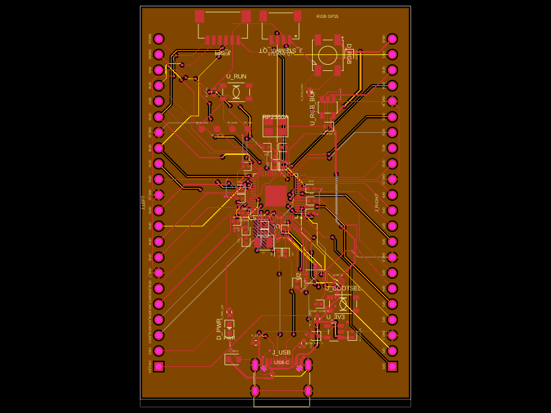 More from this authorabse/rp2350-mcu-boardThis code defines a compact, four-layer PCB hardware layout for the Raspberry Pi RP2350A microcontroller module, including the main IC, power regulation, USB-C connector, STM32-compatible headers, and associated passive components, with detailed component footprints, net connections, and copper pour zones for powering and ground references.
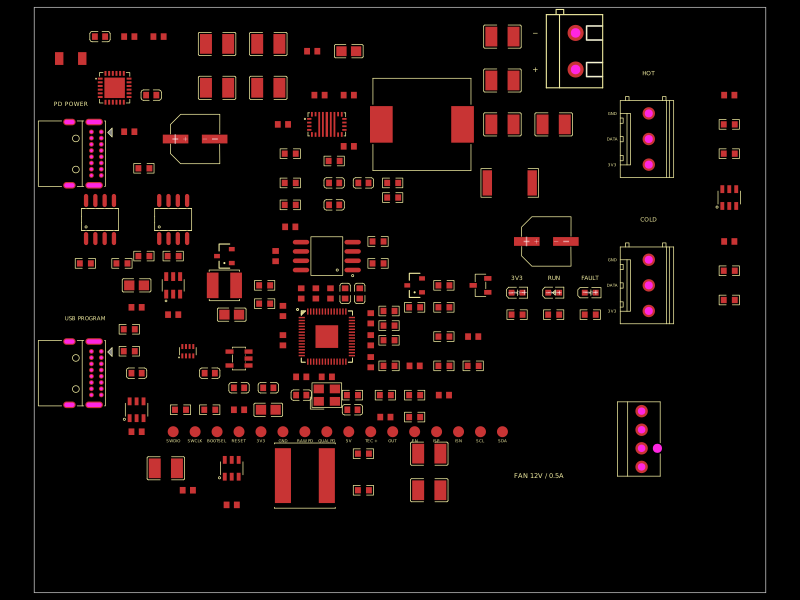 Similar package0hmX/dual-usb-peltier-assemblyA USB-C PD Peltier controller board featuring an RP2040, adjustable buck-boost TEC driver, temperature-sensor inputs, fan regulator, USB programming, protection, status LEDs, and supporting passives/connectors.
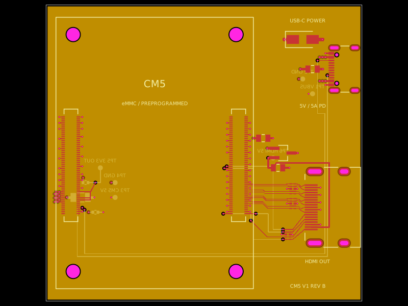 Discover something newpixalynx/cm5-minimal-carrierA 4-layer Raspberry Pi CM5 carrier board routes USB‑C 5V power through an RT9742 load switch with TVS protection and capacitive filtering, while providing ESD-protected HDMI output, CM5 connectors, test points, and ground/power planes.