MustafaMulla29/rp2040-bldc-motor-controller-new
A USB‑C PD–powered RP2040 BLDC motor controller PCB with 3.3 V logic, MCT8329A sensorless commutation, three MOSFET half-bridges, protected power switching, USB data, controls, and motor connectors.
- Version
- 0.3.82
- License
- unset
- Stars
- 0
manufacturing/motor-harness.md
# Motor connection — purchased rigid adapters

The current design uses no fabricated motor wire harness. The legacy filename is retained for factory-package references.

For each phase: Readytosky original 3.5 mm male bullet → purchased BDHI B117-5 3.5 mm female end → adapter 4 mm male end → AMASS 24.243.4 / C7437324 female PCB socket. Use three adapters, with J10 = U, J11 = V and J12 = W. Both PCB solder legs of a socket are the same contact.

Factory solder all three sockets on the top side, with the raised circular openings facing out through the top board edge. The authored PCB rotation is 90° for J10, J11 and J12; use the regenerated reviewed CPL and confirm the raised front lip in the placement preview. Preserve the authored supplier footprint and CAD orientation. The socket bodies rise 13 mm above the board, and C93 rises 16 mm above it. Allow space below for through-hole solder tails; there are no bottom component bodies. Enclosure and strain-relief design must allow plug access.

The assembly preview uses upstream male/female bullet meshes with explicitly illustrative axial/sleeve dimensions. The adapter seller has not established numerical current rating or full insertion geometry. Verify those before production use; the PCB DRC result does not establish them. See ../assembly/README.md and ../docs/offboard-parts.csv.
Related Packages
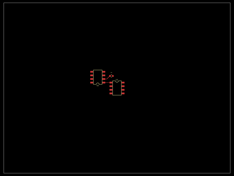 More from this authorMustafaMulla29/auto-placeA small PCB featuring two SOIC-8 ICs interconnected with a resistor.
 Similar packageimrishabh18/rp2040-motor-controllerAn RP2040-based NEMA17 stepper-motor controller with USB-C programming and PD motor-power negotiation, DRV8825 dual H-bridge drive, current/temperature telemetry, protected power filtering, status RGB LED, buzzer alarm, and optional magnetic encoder.
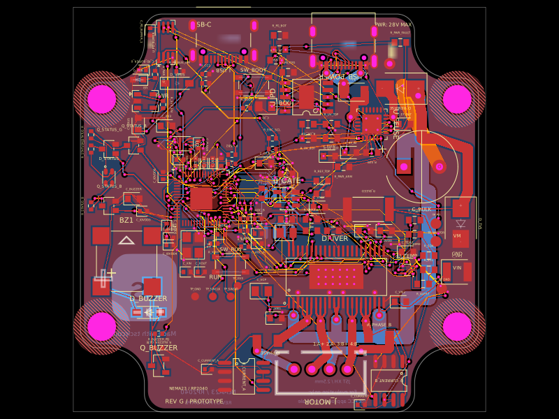 Discover something newimrishabh18/nema-23-stepper-controllerA curved NEMA23 rear-mount PCB combining an RP2040 controller, USB-C/USB-PD power input and protection, DRV8452 dual-winding stepper driver, current sensing, thermal interlock, status RGB LED, buzzer, and optional I²C encoder interface.