README.md
# Configurable USB-PD BLDC controller

Battery-free controller for the Readytosky 2212 920KV motor. **J19 PWR supports selected 5, 9, 15 or 20 V / 2 A PD contracts; 9 V remains the cold-start default. J1 DATA connects to the computer.** The illustrated motor is retained for the default setup; select a voltage appropriate to the connected motor. The two USB cables can be connected together. There is no battery, battery charger, balance connector or external temperature probe.

Power flows through the PD input switch, current shunt, fuse F1, ideal diode U12/Q7 and current-limited switch U11 to the motor bridge. U12/Q7 replace the lossy D3 diode and block motor energy from returning to USB. SW4 OFF removes motor power and clamps ARM while USB communication remains available. Voltage selection requires SW4 OFF and a discharged motor bus.

At 5 V the motor driver still needs at least 4.5 V at its pins. Cable and board losses limit usable load. The prototype policy uses a provisional 0.8 A motor-feed input ceiling and a 4.65 V measured motor-bus cutoff; neither is a validated motor rating. Use calibrated voltage readings. The supplied bring-up console deliberately keeps motor drive OFF at every setting. **The configurable-PD changes were applied to main with user approval on 16 October 2026; 5 V motor operation remains unqualified and awaits maintainer review.** The U11-only replacement evaluation did not resolve the voltage margin, so the existing U11 is retained. See [current revision](manufacturing/CURRENT-REVISION.md).

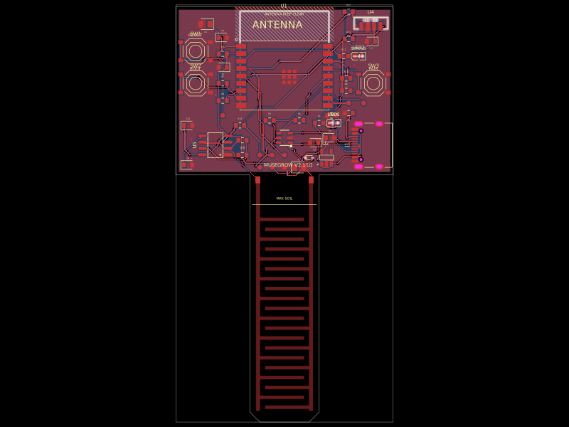
All fitted components are on the top of a **73 × 72 mm, four-copper-layer PCB**. J10/J11/J12 are outward-facing AMASS 24.243.4 sockets. The motor's original 3.5 mm male bullets plug into three purchased 3.5 mm female / 4 mm male rigid adapters, then into those sockets. RV1 speed, SW3 ARM, SW1 BOOTSEL and SW2 RESET are onboard. Sixteen copper test pads provide service access.

The assembly includes the PCB, motor, original motor leads, rigid adapters, a PD-power USB cable and a computer-data USB cable. USB source/host enclosures and cable lengths are representative. Exact motor-lead and adapter-body dimensions remain unverified; this view does not prove physical mating.

The compact layout saves **12.5% board area** compared with the previous 77 × 78 mm outline, and **27.0%** compared with 80 × 90 mm. See [layout changes](docs/compact-layout.md).

## Build and inspect

Run `bun run dev` and open **3D** for the full connected system. The default
package entrypoint is `system.circuit.tsx`; `index.circuit.tsx` remains the
PCB-only design for fabrication. Both use the same live board source.

```sh
bun run typecheck
bun run test
bun run check # strict schematic-style advisories are documented in docs/validation.md
bun run build
bun run assembly:test
bun run check:integration
bun run dev
```

`bun run build` compiles the board and integrated package using the included
assembly asset. After a board or assembly edit, use `bun run build:all` locally
to regenerate that asset and rerun the PCB audits. `circuit/route-plan.json` is
guarded against changed pads, nets or rules.
`dist/index/circuit.json` is the PCB build; `dist/system/circuit.json` adds the
external assembly. Both and their reports must be rebuilt after source changes.
A passing certificate applies only to its recorded input hash.

The main project uses the latest published tscircuit release and its normal dependency tree, with
no internal dependency overrides or CLI patches. `bun.lock` records the
installed versions; run `bun update tscircuit --latest` to refresh them.
The old upload-timeout/ignore-list patch is no longer applied. The integrated
assembly remains in `assets/connected-system.glb`.

Publish with `bun run push:package`. This prepares a temporary portable copy
using the configured exclusions, then runs the installed, unmodified `tsci push
--compress`. The current CLI's direct push does not apply `ignoredFiles`, so it
also uploads local assembly authoring tools. The helper keeps those tools locally
and includes the complete `assets/connected-system.glb` in the published package.
Use `bun run push:package --prepare-only` to inspect the copy before uploading.

## Engineering status

**Hold the current manufacturing order.** The 12 October follow-up fixes the R81 Kelvin routing and U11 native paste size. U7 now exports six native rectangular paste windows; factory stencil/process approval remains required. See the [order-readiness review](docs/order-readiness.md). Passing PCB DRC and configured width checks does not approve fabrication or motor operation.

The change is a design prototype, not a bench-qualified motor controller. The PD diagnostic firmware provisions a 9 V default and selects/checks 5/9/15/20 V over USB DATA while keeping the motor OFF. The separate `firmware/knob_app.py` now implements knob/ARM control, filtered/ramped PWM commands and calibrated power/current supervision. It ships in preview-only mode until a commissioned motor profile and measured ADC calibration are supplied. Motor tuning, coast-stop/AVS behavior and physical testing remain outstanding; no working motor operation is claimed. D4 is a transient suppressor, not a continuous regenerative braking load. See [knob firmware](docs/knob-firmware.md) for operation, commissioning and limitations.

See [connections and firmware](docs/connectors-and-firmware.md), [PD-only design](docs/pd-only-design.md), [assembly](docs/full-assembly.md) and [manufacturing status](docs/order-readiness.md). Previous battery-revision files are backed up outside this package.

Validation results and the remaining native style advisories are recorded in [validation](docs/validation.md).


The onboard **RGB STATUS** LED beside ARM uses blue for PD waiting/negotiation,
green for a verified selected PD contract and red for diagnostic errors.
The current diagnostic firmware keeps the motor OFF; green is not a motor-run
indication. See [connections and firmware](docs/connectors-and-firmware.md).