MustafaMulla29/rp2040-bldc-motor-controller-new
A USB‑C PD–powered RP2040 BLDC motor controller PCB with 3.3 V logic, MCT8329A sensorless commutation, three MOSFET half-bridges, protected power switching, USB data, controls, and motor connectors.
- Version
- 0.3.82
- License
- unset
- Stars
- 0
circuit/schematic-notes.tsx
import { Fragment } from "react"
import layout from "./schematic-layout.json"

/** Native schematic pages and functional boxes. No electrical/PCB elements.
 * Net labels are generated from trace-to-net connections, never positioned here.
 */
export function SchematicNotes() {
  return <>{layout.sheets.map(sheet => <Fragment key={sheet.name}><schematicsheet
    name={sheet.name} displayName={sheet.title} sheetIndex={sheet.index} sheetSize={sheet.name === "guide" ? "ANSI_B" : "A4"}>
    <schematictext text={`${sheet.index + 1} / ${layout.sheets.length} — ${sheet.title}`}
      schX={sheet.name === "guide" ? 0 : -13.5}
      schY={sheet.name === "guide" ? 12.78 : 9.9}
      anchor={sheet.name === "guide" ? "center" : "left"} fontSize={0.42} color="#174e70" />
    {layout.notes.filter(n => n.sheet === sheet.name).map((n, i) => <Fragment key={i}>
      {n.lines.map((text, j) => <Fragment key={j}><schematictext text={text}
        schX={n.x} schY={n.y - j * 0.44} anchor="left" fontSize={n.lines.length === 1 ? 0.30 : 0.23} color="#46556a" /></Fragment>)}
    </Fragment>)}
    {sheet.name === "bridge" && ["U", "V", "W"].map((phase,i) =>
      <Fragment key={phase}><schematictext text={`Phase ${phase} half bridge`} schX={-11.5+i*7.48} schY={7.65}
        anchor="left" fontSize={0.28} color="#174e70" /></Fragment>)}
    <schematicline x1={sheet.name === "guide" ? -22.5 : -14.7} y1={sheet.name === "guide" ? 12.15 : 9.4}
      x2={sheet.name === "guide" ? 22.5 : 14.7} y2={sheet.name === "guide" ? 12.15 : 9.4} strokeWidth={0.015} color="#aeb7c0" />
    <schematicline x1={sheet.name === "guide" ? -22.5 : -14.7} y1={sheet.name === "guide" ? -13.32 : -10.2}
      x2={sheet.name === "guide" ? 22.5 : 14.7} y2={sheet.name === "guide" ? -13.32 : -10.2} strokeWidth={0.015} color="#aeb7c0" />
    {sheet.name === "guide" && <ConnectionGuide />}
  </schematicsheet></Fragment>)}
  </>
}

function ConnectionGuide() {
  const block = (name: string, x: number, y: number, title: string, lines: string[]) =>
    <Fragment key={name}>
      <schematicbox name={name} schX={x} schY={y} width={9} height={3.6}
        title={title} titleFontSize={0.35} titleAlignment="top_center" titleInside />
      {lines.map((text,i) => <Fragment key={i}><schematictext text={text}
        schX={x} schY={y + 0.3 - i * 0.62} anchor="center" fontSize={0.3} /></Fragment>)}
    </Fragment>
  const arrow = (x1: number, y: number, x2: number) => <>
    <schematicline x1={x1} y1={y} x2={x2} y2={y} strokeWidth={0.035} color="#174e70" />
    <schematicline x1={x2-.25} y1={y+.16} x2={x2} y2={y} strokeWidth={0.035} color="#174e70" />
    <schematicline x1={x2-.25} y1={y-.16} x2={x2} y2={y} strokeWidth={0.035} color="#174e70" />
  </>
  return <>
    <schematictext text="POWER FLOW" schX={-20} schY={10.8} anchor="left" fontSize={0.4} color="#174e70" />
    {block("guide_pd",-15.6,8,"J19 / USB PD",["USB-C PD input", "PD controller: sheet 2"])}
    {arrow(-11.1,8,-9.7)}
    {block("guide_pd_feed",-5.2,8,"FUSED PD FEED",["F1 + ideal diode U12/Q7", "Motor feed: sheet 4"])}
    {arrow(-.7,8,.7)}
    {block("guide_switch",5.2,8,"SW4 / MOTOR POWER",["Current-limited U11", "Power switching: sheet 3"])}
    {arrow(9.7,8,11.1)}
    {block("guide_motor",15.6,8,"BRIDGE → MOTOR",["J10/J11/J12: U/V/W", "Power stage: sheet 9"])}
    <schematictext text="CONTROL / PROGRAMMING" schX={-20} schY={4.8} anchor="left" fontSize={0.4} color="#174e70" />
    {block("guide_data",-15.6,2,"J1 / DATA 5V",["Computer USB cable", "USB / debug: sheet 5"])}
    {arrow(-11.1,2,-9.7)}
    {block("guide_mcu",-5.2,2,"RP2040",["Firmware / supervision", "Processor: sheet 6"])}
    {arrow(-.7,2,.7)}
    {block("guide_driver",5.2,2,"MCT8329A",["Motor commutation", "Driver / inputs: sheet 7"])}
    {block("guide_logic",15.6,2,"3.3 V LOGIC",["PD or DATA USB supply", "Source isolation: sheet 3"])}
    <schematictext text="PLUG-IN CONNECTIONS / CONTROLS ON SHEET 8" schX={-20} schY={-1.9} anchor="left" fontSize={0.4} color="#174e70" />
    <schematictext text="SUPPLY" schX={-20} schY={-3.2} anchor="left" fontSize={0.34} />
    <schematictext text="USB-C PD supply → J19. Select 5 / 9 / 15 / 20 V through J1 DATA. Default: 9 V."
      schX={-15.5} schY={-3.2} anchor="left" fontSize={0.3} />
    <schematictext text="Computer USB cable → J1 DATA. J1 cannot power the motor; both USB cables may be connected."
      schX={-15.5} schY={-3.9} anchor="left" fontSize={0.3} />
    <schematictext text="MOTOR" schX={-20} schY={-5.2} anchor="left" fontSize={0.34} />
    <schematictext text="Readytosky 2212 920KV → three purchased BDHI B117-5 adapters → J10/J11/J12 sockets."
      schX={-15.5} schY={-5.2} anchor="left" fontSize={0.32} />
    <schematictext text="3.5 mm female / 4 mm male rigid adapters; factory-fitted sockets. No harness fabrication."
      schX={-15.5} schY={-5.9} anchor="left" fontSize={0.32} />
    <schematictext text="CONTROLS" schX={-20} schY={-7.2} anchor="left" fontSize={0.34} />
    <schematictext text="RV1: speed knob. SW3: ARM. SW4: motor POWER. All controls are fitted directly on the PCB."
      schX={-15.5} schY={-7.2} anchor="left" fontSize={0.32} />
    <schematictext text="Power / ground symbols and matching signal names join the same net across sheets."
      schX={-20} schY={-9.4} anchor="left" fontSize={0.32} color="#46556a" />
    <schematictext text="Change voltage with SW4 OFF. Require the selected PD contract and deliberate ARM."
      schX={-20} schY={-10.2} anchor="left" fontSize={0.32} color="#46556a" />
    <schematictext text="Firmware and hardware qualification pending. Setup: docs/connectors-and-firmware.md."
      schX={-20} schY={-11.4} anchor="left" fontSize={0.3} color="#46556a" />
  </>
}
Related Packages
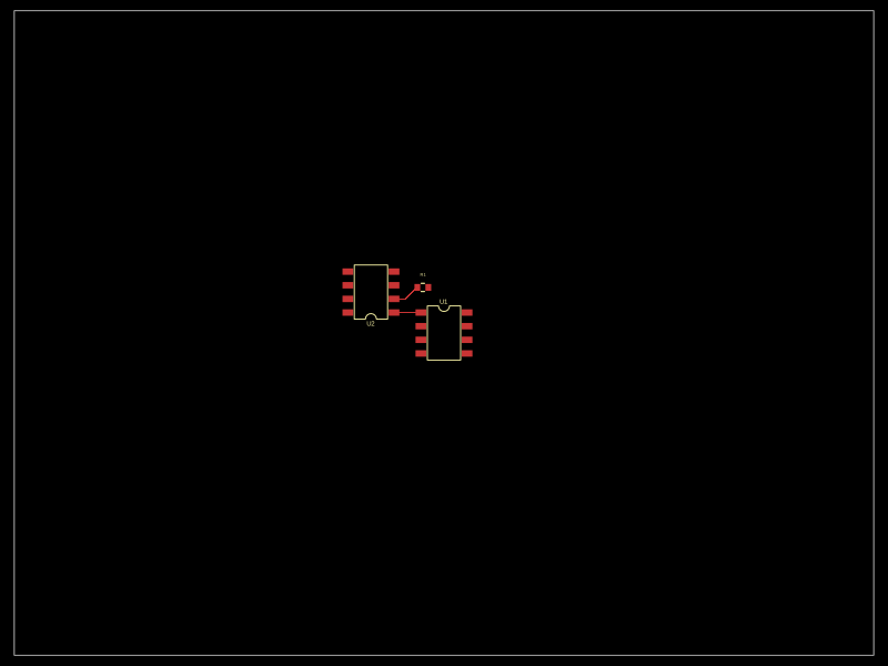 More from this authorMustafaMulla29/auto-placeA small PCB featuring two SOIC-8 ICs interconnected with a resistor.
 Similar packageimrishabh18/rp2040-motor-controllerAn RP2040-based NEMA17 stepper-motor controller with USB-C programming and PD motor-power negotiation, DRV8825 dual H-bridge drive, current/temperature telemetry, protected power filtering, status RGB LED, buzzer alarm, and optional magnetic encoder.
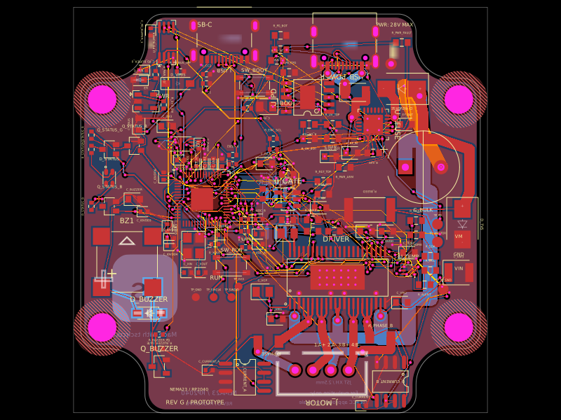 Discover something newimrishabh18/nema-23-stepper-controllerA curved NEMA23 rear-mount PCB combining an RP2040 controller, USB-C/USB-PD power input and protection, DRV8452 dual-winding stepper driver, current sensing, thermal interlock, status RGB LED, buzzer, and optional I²C encoder interface.