AnasSarkiz/magnetic-shutter-remote-r8
A USB‑C rechargeable battery-powered ESP32‑C3 wireless controller with Li‑ion charging, protected 3.3‑V buck‑boost regulation, thermal/safety monitoring, status LEDs, buttons, programming UART, crystal clock, and 2.4‑GHz antenna matching network.
- Version
- 0.4.0-prototype
- License
- unset
- Stars
- 0
scripts/write-r6-documents.py
"""Create R6 release notes from checked artifact metrics, without altering PCB."""
from pathlib import Path
ROOT=Path(__file__).resolve().parents[1]
def write(path,text):
 p=ROOT/path;p.parent.mkdir(parents=True,exist_ok=True);p.write_text(text.strip()+'\n')
write('README.md','''# Magnetic shutter remote — R6

**ENGINEERING PROTOTYPE — NOT PRODUCTION QUALIFIED**

Original detachable Bluetooth camera shutter remote and magnetic phone grip. USB-C charges an externally fitted protected single-cell battery; the separate fill light is outside scope. This is an original enclosure, not a JJC replacement board.

R6 uses **GCT USB4215-03-A / C37616412**. All 37 fitted components are imported JLCPCB parts on TOP. The PCB is **36 × 56 × 1 mm**, two layers. Editable entry point: `index.circuit.tsx`; circuit: `src/remote-circuit.tsx`. Supported imports are in `imports/`, exact identities/dates/links in `BOM.csv`, `BOM.md`, `bom.json`.

**PROTOTYPE MANUAL REWORK MAY BE REQUIRED FOR FOUR USB SHELL ANCHORS.** Exact production stencil/profile/shell-process qualification is pending. This user-authorized prototype disposition replaces the earlier supplier-response fabrication hold. It does not certify a production process.

See [qualification](R6-QUALIFICATION.md), [R5-to-R6 changes](R6-CHANGES.md), [validation](VALIDATION.md), [fabrication files](fabrication/R6/README.md), [mechanical design](mechanical/README.md), [external items](EXTERNAL-PARTS.md), [firmware](firmware/README.md) and [issue index](tscircuit-issues/README.md).

## Reproduce locally

Use Bun 1.3.9, TypeScript 5.9.3, the local locked archives and Python 3.14.7. From this directory:

```sh
bun install --frozen-lockfile
python3 -m venv tooling/gerber-review-venv
tooling/gerber-review-venv/bin/pip install -r tooling/gerber-review-requirements.txt
python3 scripts/validate-r6.py
bun scripts/render-r6-review.ts
```

The checks retain native routing and errors; the output suite regenerates the complete CAM/BOM/CPL/drawings from that build. `scripts/check-r6-preservation.py` needs the original R4/R5 directories for its read-only historical comparison; the frozen manifest and result are included for other machines. No commands above order or publish anything. The complete tool versions, source archives and patches are in `tooling/R6-README.md` and `evidence/R6/toolchain-manifest.json`.

For native interactive views: install the locked `tooling/runframe` dependencies, then run `tooling/runframe/node_modules/.bin/vite --config preview/vite.config.mjs --port 3028`. The preview displays the exact built Circuit JSON using native tscircuit PCB/Schematic/3D viewers; it is not a second board editor/compiler.

Battery, RF, thermal, runtime, enclosure fit and native-camera phone checks remain **POST-PROTOTYPE PHYSICAL VALIDATION**. No hardware has been tested, ordered, uploaded or published in this run.
''')
write('R6-CHANGES.md','''# R5 → R6 engineering changes

R5 directory and its 556 protected files are preserved. R4's 416 files are also preserved: 972/972 hashes unchanged. R6 is isolated in `magnetic-shutter-remote-r6--01a0f81f`, branch `r6-usb4215-engineering-prototype`; baseline provenance is `evidence/R6/START-FROM-R5.json`.

- J1: HCTL HC-TYPE-C-6P-01A / C2894893 → GCT USB4215-03-A / C37616412. Generated through the corrected supported importer, never hand-edited. Manufacturer Rev A land/slot drawing is authoritative.
- J1 authored anchor (0,23.9852), TOP rotation 180°. Actual component/CPL centroid (0,24.5101989); mating face Y=28.6601694. The face moved 0.60 mm outward from the R5 mouth alignment. All 36 other placements and non-USB connections remain identical.
- USB opening: 12 × 7 → 12 × 9.5 mm; same front wall, same centre Y=29/Z=8. Remote body, PCB outline, charger, battery, radio, buttons, firmware and dock geometry unchanged.
- Explicit CC1/CC2 nets terminate on pins 20/26; VBUS on 18/27; GND/shield on 13–17/28. Data/SBU contacts explicitly unconnected. Charging remains reversible.
- Native USB escape path starts follow the new lands; prior escape exits/via sizes remain. Shell escape crossings corrected to nearest-side exits.
- 161 TOP paste apertures total (151 − 6 old USB + 16 new USB); J1 has 12 contact and four shell polygons, mask expansion 0.0508 mm.
- Strict assembly export extended generically for footprints without numeric pin1. The exact supplier model verifies all 16 terminal positions and the unique rotation; no synthetic pin1 or edited component metadata.
- Compatible CLI source build integrates the qualified polygon-paste exporter. Required shorts check now passes, with an injected-short regression that fails correctly.

## Routing scope and unavoidable changes

The semantic geometry comparison in `evidence/R6/R5-to-R6-comparison.json` identifies each path. 60/139 traces retain exact geometry; 79 paths changed. All non-USB saved fanouts remain exact. Native global followup routing reran after USB terminal geometry changed; it did not change the other component placements or circuit functions. The current public route-cache API cannot serialize branched followups (issue 014). A native preloaded-route probe rejected the old routing graph; both its input and failure log are preserved. No generated routing/JSON/CAM was patched to force preservation. Independently checked regenerated copper, ground continuity and RF keepouts pass.

## Prototype disposition

**ENGINEERING PROTOTYPE — NOT PRODUCTION QUALIFIED.** Production profile/stencil/shell-joint coverage remain pending, with user-authorized inspection and possible manual shell rework for the first boards. Published heat-resistance numbers are not relabelled as a production profile. R5 is not retroactively promoted. Nothing was ordered or published.
''')
write('R6-QUALIFICATION.md','''# R6 engineering prototype qualification

**ENGINEERING PROTOTYPE — NOT PRODUCTION QUALIFIED**

## J1 geometry and electrical mapping

GCT USB4215-03-A / C37616412; official Rev A drawing/specification dated 2024-04-26. Supplier UUID 3104977db58742e399663286e4a66eac. Copper, slots and terminal centres match the manufacturer drawing; successful import alone was not used as qualification. Exact measured source/CAM values are in `evidence/R6/manufacturing-review.json`; original audit in `evidence/USB4215-import-audit/`.

| Feature | Actual geometry mm | GCT reference |
|---|---|---|
| Eight narrow contact lands | 0.2999994 × 1.1999976 | width 0.30, length 1.15 ±0.05 |
| Four wide power/GND lands | 0.5999988 × 1.1999976 | width 0.60, length 1.15 ±0.05 |
| Rear shell slots, local X ±4.319905 / Y +1.4250226 | hole 0.5999988 × 1.3999972, copper 0.999998 × 1.7999964 | hole 0.60 ×1.40, copper1.00 ×1.80 |
| Front shell slots, same X / Y −2.5749694 | hole0.5999988 ×1.7999964, copper0.999998 ×2.1999956 | hole0.60 ×1.80, copper1.00 ×2.20 |
| Contact pitch | nominal 0.50 | official recommended PCB layout |
| Mask | source expansion0.0508 on all16 lands | supplier setting; independently exported/clearance checked |
| Paste | 16 separate TOP polygons | exact unmodified supplier CAD |

Local geometry rotates 180° at the authored anchor. All four plated slots are represented as G85 Excellon slots and read back by a slot-capable reader. No NPTH locating holes are added for J1.

| Imported terminal | Manufacturer contact | Circuit |
|---|---|---|
| 13,14,15,16 | EH2,EH1,EH3,EH4 shell anchors | GND |
| 17 /28 | A1B12 /B1A12 | GND |
| 18 /27 | A4B9 /B4A9 | USB5V |
| 20 /26 | A5 /B5 | CC1 /CC2, each independent5.1kΩ Rd |
| 19 /25 | B8 /A8 | SBU2 /SBU1, noConnect |
| 21 /23 | B7 /A7 | D−, noConnect |
| 22 /24 | A6 /B6 | D+, noConnect |

USB data are unused; charging and CC work in both plug orientations by documented paired VBUS/GND and separate Rd contacts. Physical insertion and source negotiation are unperformed prototype tests.

## Completed software/design evidence

- Native source/netlist/pin-specification/schematic-placement/placement, routed build and shorts checks: recorded commands/exits in `evidence/R6/suite-exits.json`.
- Classified manufacturing clearances (pads, plated slots, round/NPTH holes, vias, traces and pours): no failures in `copper-audit.json`. No lowered rule thresholds or same-footprint exemptions.
- 12 CAM files, full outline/drills/slots/layers read back; `cam-readback/readback.json`. BOTTOM paste is empty because all37 fitted parts are TOP.
- 37/37 source → Circuit JSON → BOM/CPL → assembly PDF registrations. J1 unique180° supplier-terminal pose checks16/16 positions; others retain strict supplier pin1 checks. Independent Python recheck agrees.
- J1 paste16/16, no duplicate/merged shapes; max contour difference0.000000565686mm. Total161TOP apertures, no missing coverage, no mask/outline violations.
- 0.10mm stencil retained. Worst area ratio0.6999986; aspect1.999996. These are calculated release metrics, not physical transfer measurements. EP coverage is explicitly recorded and not used alone as a pass/fail surrogate.
- Solid continuous TOP GND includes BQ25185 GND and full exposed pad; all GND SMT lands physically connected; lateral GND vias connect bottom plane; no via-in-pad. Correct TI SLUSF65B, August2026, §7.4.1/Fig7-9. No RF keepout intrusions. Thermal performance pending.
- Actual functional silkscreen clears mask/outline, minimum glyph height1.129158mm/stroke0.18mm. BAT +/−, shutter/pair/power and SWD orientation/pin functions retained.
- Firmware rebuilt against unchanged final GPIO assignments: FLASH164660bytes, RAM26796bytes; source HEX/BIN/debugELF hashes recorded. BLE HID Consumer Volume Increment, 60ms press/release, pairing/bond control. Compile success does not prove camera compatibility.
- Focused importer regression7,685assertions PASS. 33 baseline full-suite failures remain; full importer suite is NOT claimed passing. PNP55tests/347assertions; CLI polygon-paste/injected-short regression2tests/3assertions; current board regression totals in final log.
- Native PCB TOP/BOTTOM, all3A4schematic sheets, 3D, high-zoom J1, actual CAM copper/mask/paste and mechanical/PDF views reviewed. Native viewer limitations/warnings are recorded, never substituted for CAM metrology.

## Mechanical fit

PCB36×56×1mm; body40×60×16.8mm; USB opening12×9.5mm; grip68×108mm. GCT body8.94×6.50×3.16nominal, manufacturer general tolerance gives9.19×6.75×3.41max. Nominal mouth axisZ7.48; worst plug vertical opening clearance0.08mm, horizontal connector clearance1.105mm, plug shoulder engagement margin0.3601694mm, battery-to-USB body worst clearance0.2101694mm. Manufacturer maxima plus explicitly allocated PCB/print/location tolerances are in `usb-mechanical-fit.json`; these are calculations, not measured print tolerances. Tight margins require physical fit testing. Actual STL carrier side gap0.55mm and dock stop0.299999996mm. Original engineering dimensions, not JJC internal measurements.

## Sourcing and assembly

37fitted refs/24exact identities, all imported JLCPCBparts. J1 live official JLClisting2026-10-03:125stock,43orderable,Extended SMT,Economic/Standard,MSL1. No reservation or guarantee of future stock. Other unchanged identities retain dated R5 sourcing records; no invented substitutions. U1Standard/X-ray requirement remains recorded in BOM; choose Standard PCBA as required. 59native vias below0.3mm trigger documented extra fabrication charge, not a DRC error.

**PROTOTYPE MANUAL REWORK MAY BE REQUIRED FOR FOUR USB SHELL ANCHORS.** The four source shell paste shapes prove supplier CAD intent, not exact GCT/JLC process approval. Inspect and document all four joints on arrival; production stencil/profile/cycle/secondary-solder constraints and exact assembler coverage remain **PRODUCTION PROCESS QUALIFICATION PENDING**.

Battery safety/thermal lag, RF, current/runtime, magnetic/enclosure/cable fit, and native iPhone/representative Android camera behavior remain **POST-PROTOTYPE PHYSICAL VALIDATION**. No physical passes are claimed. USB4216 remains HOLD—ZERO STOCK/UNSUPPORTED CAD MODEL; not used and no new search performed.
''')
write('fabrication/R6/README.md','''# R6 first engineering prototype files

**ENGINEERING PROTOTYPE — NOT PRODUCTION QUALIFIED**

- `R6-gerbers.zip`:12matched CAM files (two copper, two mask, two paste, two silkscreen, F_Fab, outline, plated drill with four slots, NPTH drill).
- `JLCPCB-BOM.csv` / `JLCPCB-CPL.csv`:37TOPfitted references; exact MPN/C-number and verified rotations; centre origin(+Xright,+Yup). No external battery/magnets in assembled BOM.
- `ASSEMBLY-DRAWING.pdf`:TOPimage and37exact centroid/rotation rows.
- `BOARD-DIMENSIONS.pdf`:PCB and revised USB opening; original engineering design.

Two-layer FR4,36×56×1mm, white legends, documented0.10mm stencil strategy. Manufacturing checker rules/cost exceptions are in the qualification record. Use the Standard PCBA flow required by U1/X-ray; J1 itself is Extended SMT. Recheck ordering stock/options if an order is later authorized. No ordering/upload has occurred.

**PROTOTYPE MANUAL REWORK MAY BE REQUIRED FOR FOUR USB SHELL ANCHORS.** Inspect all four plated-slot shell joints after assembly, before trusting insertion/removal loads. Follow `PROTOTYPE-BRINGUP.md`. Missing exact production profile/cycle/manual limits and automatic shell coverage are accepted engineering-prototype uncertainties only, tracked in `PRODUCTION-QUALIFICATION-TODO.md`.

Software/design/CAM checks support a first engineering prototype, not production release or hardware-tested status.
''')
write('fabrication/R6/PRODUCTION-QUALIFICATION-TODO.md','''# Production process qualification pending

These are NOT blockers for the user-authorized first engineering prototype; they prevent production-process claims.

| GCT published parameter | Value | Current interpretation | Production limit |
|---|---|---|---|
| Peak |255–260°C|heat-resistance test|UNCONFIRMED|
| Above217°C |60s|heat-resistance test|UNCONFIRMED|
| Above230°C |50s|heat-resistance test|UNCONFIRMED|
| Above250°C |5s|heat-resistance test|UNCONFIRMED|
| Permitted reflow cycles |not found|not documented|PENDING|

Exact source: GCT USB4215 RevA specification,2024-04-26. Do not apply these numbers as an approved production recipe.

For commercial production obtain exact-part manufacturer stencil/contact/shell paste recommendation, production peak/dwell/TAL/ramp/preheat/cycle limits, whether all four shell anchors are intended for reflow and any permitted secondary process after SMT (iron maximum/time/repeat count). Independently obtain assembler confirmation that C37616412's12contact+4shell features receive paste and all four shell joints are completed, plus exact special-service options if needed. Supplier CAD intent and Extended SMT listing do not prove complete shell-joint coverage.

Prototype inspection/rework results must be recorded before selecting a volume-production flow. Do not reinterpret absent supplier replies as approval. No outreach performed during R6.
''')
write('fabrication/R6/PROTOTYPE-BRINGUP.md','''# First-board bring-up — pending physical validation

**ENGINEERING PROTOTYPE — NOT PRODUCTION QUALIFIED**

**PROTOTYPE MANUAL REWORK MAY BE REQUIRED FOR FOUR USB SHELL ANCHORS.**

1. Identify board/source/firmware revision and assembly options. Inspect microscope images of12J1contacts and all4shell-slot joints, BQ25185 lead/EP solder and other polarities. Meter unpowered USBVBUS/GND and battery polarity; confirm no shorts. Check continuity of EACH shell anchor to GND (shell-to-shell continuity alone is insufficient evidence that each individual anchor is soldered).
2. If shell fill/wetting is incomplete, record the exact defective joint and before/after images. The user accepts prototype manual touch-up risk; GCT's permitted iron/time/repeat limits are not documented. An experienced technician must choose and record a controlled exploratory rework process, temperature/contact time/cycles and resulting inspection; this project provides no invented safe temperature limit or approved procedure. Recheck all four joints/shorts after any touch-up. Do not apply cable mechanical loads until the shell is secured.
3. With battery disconnected, apply a current-limited regulated5V source to USB. Test both plug orientations with compliant C-to-C and A-to-C sources; record CC1/CC2behavior, VBUS/SYS/V3 and USB-present radio-disable behavior. D+/D−/SBUare intentionallyunused; check these contacts remain isolated rather than testing USBdata enumeration.
4. Before connecting DTP401525(PHR), meter red/black and PHcavity polarity against J2markings/drawing. Verify the actual pack, insulation, strain relief, protection and dimensions. Fit thermal interface without hard pouch pressure. Connect with limited/supervised first charge; measure chargecurrent, regulation/termination, railvoltage and temperature; verify temperature-controlled charge inhibition and protection behavior within the documented cell/board limits. Do not deliberately abuse the cell to test a destructive fault.
5. With USBdisconnected, verify regulator3.0V and powercontrol/reset. Program the fresh firmware via the documented JSTSHSWDpinout using Vrefas sense-only; confirm debugger orientation. Measure idle/advertising/connected/shot current and runtime using a stated duty cycle.
6. Pair native iPhoneCamera and a representative AndroidCameraapp; record exact phone, OS, app/version, still/video modes and whether HIDVolumeIncrement triggers the expected action. Verify press/release/no-repeat, reconnect, bondclear and pairing indications. Other cameraapps may behave differently; no universal compatibility claim.
7. Fit measured printed base/lid and actual cable. Test insertion/removal in bothorientations, plug shoulder clearance,4shell-joint mechanical integrity, battery/wire/plunger/slider tolerances, screw exclusion, docking motion and magnetretention/drop behavior. Tight calculated USBopeningmargin0.08mm must be physically checked.
8. Measure RFrange/RSSI in detached and docked use with intended phone, battery, receiverplate, magnets and fasteners. Check thermal gradients/temperaturelag and long-term runtime. Record failures, accepted rework and required nextrevision.

All these remain **POST-PROTOTYPE PHYSICAL VALIDATION**. The estimates and softwarechecks in R6do not count as physicalpasses. No productionqualification or regulatory/Bluetoothcertification is claimed.
''')
Related Packages
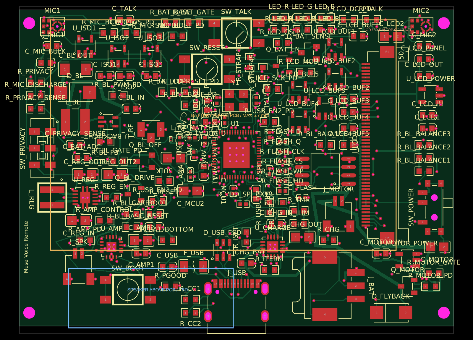 More from this authorAnasSarkiz/muse-voice-remoteMuse Voice Remote v1.3.0: checked prototype PCB/PCBA handoff. Bare ESP32-S3R8 chip, 155 TOP parts from 56 stocked JLCPCB imports with supplier CAD retained. Exact ER-TFT028A2-4 no-touch LCD, dual microphones, TALK, physical privacy, Wi-Fi, speaker, haptic and USB-C. Includes circuit.json, Gerbers/drills, JLC BOM/CPL, segmented stencil artwork and 19 filled/capped thermal-hole map. Native/factory DRC clean; 20 tests pass. See manufacturing/FABRICATION-NOTES.md for stackup and assembly requirements. Physical device/enclosure/RF qualification, firmware and connected-service MUSE integration remain unverified.
 Similar packageaura/diy-power-delivery-triggerThis hardware design implements a USB Type-C port with supporting power management and signal conditioning components, including a USB-C connector, a FUSB302 USB-C port controller, ESD protection diodes, a buck converter for 3.3V power regulation, an STM32 microcontroller for control and processing, an RGB LED indicator, push button, terminal block connections, and associated filtering and support components.
 Discover something newseveibar/am3352-ram-dogbone-and-single-layer-route-testAM3352BZCZ100 processor connected to a W631GG6MB-12 DDR3 memory chip through a routed, length-matched 16-bit DDR interface with clock/data-strobe pairs and control/address signals.