0hmX/esp32-s3-usb-webcam-ov2640
This code defines and integrates a variety of surface-mount, through-hole, and connector hardware components (including microcontrollers, regulators, resistors, capacitors, and connectors) into a PCB design framework, enabling schematic symbol creation, footprint definition, and automated routing within an electronic circuit layout.
- Version
- 1.0.7
- License
- unset
- Stars
- 0
COMPACTNESS_REPORT.md
# PCB compactness experiment report

## Outcome

The best fully validated result is **65.5 mm × 42.5 mm** (**2,783.75 mm²**),
which is **9.03% less board area** than the 68 mm × 45 mm baseline. It keeps:

- all 59 source components;
- the original four mounting holes;
- four copper layers;
- top-side component assembly only;
- the existing USB, ESP32-S3, camera, debug, reset, and boot functions; and
- every electrical pad at its already validated coordinate.

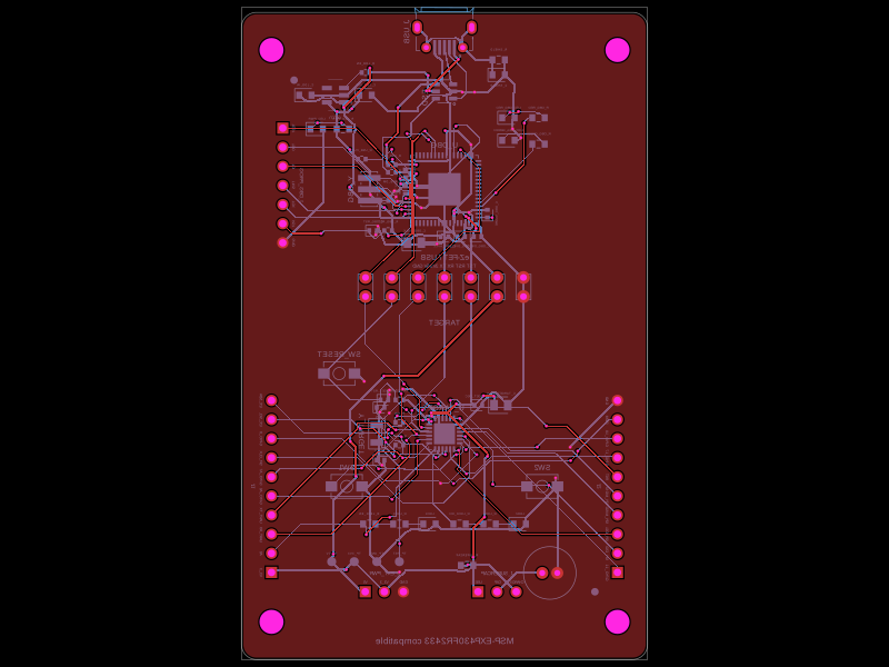
The accepted build contains **149 PCB traces and 151 vias**, with **zero Circuit
JSON errors and zero detected shorts**. TypeScript, unit tests, netlist,
schematic placement, PCB placement, routing-difficulty, full build, and shorts
checks all pass.

## What was tried

| Candidate | Area reduction | Main constraints | Result |
| --- | ---: | --- | --- |
| 68 × 45 mm baseline | 0% | Original design | Clean control: 149 traces, 151 vias, zero errors, zero shorts |
| 67 × 44 mm native crop | 3.66% | Original coordinates and four holes | Fully routed, but 17 PCB errors and 6 confirmed shorts; rejected |
| 66 × 43 mm native crop | 7.25% | Original coordinates and four holes | Router left 133 endpoints unconnected; rejected |
| **65.5 × 42.5 mm proven-route crop** | **9.03%** | Original coordinates, four holes, top-side assembly | **Clean and accepted** |
| 65 × 43 mm moved-hole crop | 8.66% | Holes moved inward; post-build copper transformation | Placement-clean, but fresh routing failed and final transformed result was not fully signed off; rejected |
| 64 × 40 mm compact crop | 16.34% | All major functions retained | 149 routes could be produced, but camera-region copper had 3 confirmed shorts; rejected |
| 58 × 38 mm dense layout | 27.97% | All 59 components, four holes, top-side assembly | Placement-clean, but every attempted routing strategy ran out of iterations; rejected |
| 55 × 36 mm balanced redesign | 35.29% | All functions, four holes, top-side assembly | Full route completed, but 10 shorts remained around camera rails/SCCB/FPC breakout; rejected |
| 48 × 32 mm aggressive redesign | 49.80% | Two holes, bottom-side parts, smaller passives | Placement/netlist-clean, but `CAM_SDA` was unreachable and routing did not complete; rejected |

These results separate three different meanings of “compact”: a placement that
fits, a router that finishes, and a fabrication candidate that is actually
short-free. Only the accepted 65.5 × 42.5 mm result satisfies all three without
changing the product or assembly constraints.

## Why the accepted route is deterministic

Shrinking only the outline does not move any pad. Fresh autorouting nevertheless
changed its search result between builds and introduced shorts even in the mild
67 × 44 mm crop. The accepted design therefore reuses the **128 autorouted
traces** from the already short-checked baseline, alongside the 21 source-native
manual traces. This happens inside the normal tscircuit render; it is not a
post-build Circuit JSON patch. Tscircuit still regenerates the compact board,
copper pours, previews, and DRC output.

An endpoint guard compares every routed `pcb_port_*` coordinate with the proven
reference before returning copper. Moving a connected component or pad makes
the build fail loudly until the route is deliberately regenerated. The stored
reference contains only the 128 required trace records rather than a complete
generated circuit artifact.

This is an appropriate optimization for a frozen placement, but it has a clear
maintenance cost: future placement changes require a new route and the complete
validation sequence below.

## Mechanical limits of the accepted outline

The four 2.7 mm non-plated mounting holes remain at `(±30.5, ±19.0) mm`. The
drill edge is **0.90 mm** from each adjacent board edge. The rightmost JTAG
1.2 mm pad has **2.15 mm** of pad-edge clearance to the board edge. PCB
placement reports no overlap or out-of-bounds errors.

The outline should not be reduced further with the current hole coordinates.
Even if a software check accepts a smaller value, the mounting-hole edge margin
quickly becomes mechanically unattractive. A smaller product should explicitly
move or remove holes and then be reviewed against the chosen fabricator’s
rules, enclosure, screw-head/washer geometry, and board-edge strength.

## Validation record for the winner

| Gate | Result |
| --- | --- |
| `bun run typecheck` | Pass |
| `bun test` | 7 passed, 91 expectations |
| `bunx tsci check netlist index.circuit.tsx` | 0 errors, 0 warnings |
| `bunx tsci check schematic-placement index.circuit.tsx` | Pass; one optional reset-trace simplification suggestion |
| `bunx tsci check placement index.circuit.tsx` | 0 errors, 0 warnings; 37.253% top utilization |
| `bunx tsci check routing-difficulty index.circuit.tsx` | Pass; maximum reported difficulty 7.5% |
| `bunx tsci build index.circuit.tsx --pcb-png` | Pass |
| Generated Circuit JSON | 149 traces, 151 vias, 11 copper pours, 0 error records |
| `bunx tsci check shorts index.circuit.tsx` | No shorts detected |
| Visual PCB review | No clipped copper or components observed |

## If a substantially smaller board is still required

A credible next target is roughly **58 × 38 mm**, but it is a redesign rather
than an outline crop. Before attempting it again:

1. Decide whether two mounting holes and bottom-side assembly are acceptable.
2. Hand-route the complete camera FPC breakout, including DVP, SCCB, clocks,
   resets, and all three camera rails, before placing the remaining passives.
3. Move the camera connector and ESP32 module as a coordinated pair so the
   camera bus does not cross the rail fanout.
4. Review every 0402/0603 substitution and smaller power/USB part against
   voltage, current, availability, assembly yield, and rework requirements.
5. Preserve the ESP32 antenna keepout, continuous USB reference, and camera
   return paths; do not trade signal integrity for outline area.
6. Re-run all checks plus controlled-impedance review, enclosure verification,
   camera pin-1/orientation inspection, and hardware streaming tests.

The 48 × 32 mm experiment shows that nearly 50% area reduction is geometrically
possible, but not with the present routing topology and mechanical/assembly
requirements. The clean 9.03% crop is therefore the best result obtained from
the current design without increasing product risk.