tscircuit/standard-jst-programmer
26 × 42 mm USB-C RP2040 programmer with JST and TC2030 IDC SWD, NRST, selectable sensed 5 V / 3.3 V power, RGB status, and importable JST SH/Tag-Connect targets. Top-side assembly.
- Version
- 0.8.0
- License
- unset
- Stars
- 0
FABRICATION.md
> UART source revision v0.8.0: the current `ProgrammerBoard` is 26 × 42 mm and adds J5
> (SM03B-SRSS-TB, C160403), host pin order TX/GND/RX, plus two 100-ohm UART
> resistors. The v0.7.1 fabrication ZIPs described below are historical and do not
> contain UART. Build and run `npm run export:fabrication` from the new source
> before producing revised manufacturing files.

# Standard JST programmer v0.7.1 — fabrication package

Source: https://tscircuit.com/tscircuit/standard-jst-programmer, release 0.7.1
Registry release ID: 42e3cd0d-cfd0-4d2a-a0ea-b02aa3ca064c.
Revised September 29, 2026 from the programmer circuit only, excluding the example boards.

## Revision changes

The published hardware revision is v0.7.1, based on registry release 0.7.0. All 98 vias use 0.30 mm drills and 0.55 mm copper pads. Saved routes were adjusted for the larger vias, retaining the board dimensions, connectivity, and clearance rules. The bottom silkscreen includes `standard-jst-programmer` and `v0.7.1` as three uppercase lines in an open back-side area, clear of the connector legends and via openings.

The label reads `projectName` and `version` from `tscircuit.config.json`. The built-in `printBoardInformationToSilkscreen` option is disabled because this installed tscircuit version hardcodes that automatic label to the top layer. The explicit bottom label remains automatic with respect to the config values. Export checks require the back label, package/config version agreement, 0.30 mm drill sizes, and pads of at least 0.55 mm; they also reject a 0.20 mm drill tool in the exported drill files.

The website preview now renders the standalone programmer. Its bottom ground pour matches the fabrication copper: one continuous region connected to all 27 ground vias. The connector examples remain separate circuits.

## Fabrication

Upload `standard-jst-programmer-v0.7.1-gerbers.zip` for bare PCB fabrication. It contains four copper layers, top/bottom solder mask and paste, silkscreen, outline, fabrication drawing, and plated/non-plated Excellon drill files.

- Board: 26 × 42 mm, FR-4, four copper layers, source-defined thickness 1.4 mm.
- Layer order: F_Cu, In1_Cu, In2_Cu, B_Cu.
- Drill span: L1–L4 through holes; no blind/buried drill files.
- Minimum configured trace width: 0.10 mm; trace-to-pad clearance: 0.12 mm.
- Minimum configured via: 0.30 mm drill / 0.55 mm copper diameter (0.125 mm annular ring).
- Configured pad-to-pad clearance: 0.10 mm; board edge clearance: 0.20 mm.
- Coordinates: millimetres, board center (0,0), +Y upward in Gerbers and both CPL files.
- Copper weight, finish, solder-mask color, and dielectric stackup are not specified by the source; choose these with the fabricator.

## Assembly files — review required

`assembly/BOM.csv` and the CPL files contain the same 60 top-side components.
`CPL-pcb-rotations.csv` uses authored PCB rotations. `CPL-jlcpcb-REVIEW-REQUIRED.csv` applies supplier orientation corrections where available; unresolved rows retain the authored rotation and require review.

The current parts engine cannot verify supplier rotations for J_USB, D_PWR, L_AVDD, SW_PWR, and J4. See `assembly/rotation-review.json`. Verify these five orientations in the assembler's preview before releasing assembly. Supplier footprint lookups also failed for L_AVDD (C1002) and J4 (C3324375), so confirm the BOM parts. L_AVDD is intended as a 600-ohm-at-100-MHz ferrite bead, not a 600-MH inductor; its BOM comment states that intent. No substitute part has been selected.

The build reports geometric differences between generic 0402 passive footprints and supplier footprints, missing pin-attribute/courtyard metadata, two unused USB SBU pins, and unnamed traces. Full warnings are retained in `validation/`. The dense source silkscreen is retained; use the assembly drawing for component identification.

JST J1/J2/J3 have matching supplier orientation metadata and no JST footprint, accessibility, or DRC errors. Pin assignments were checked:

| Ref | Part | Pin order |
|---|---|---|
| J1 | SM03B-SRSS-TB(LF)(SN), C160403 | SWCLK, GND, SWDIO |
| J2 | SM02B-SRSS-TB(LF)(SN), C160402 | VOUT, GND |
| J3 | SM05B-SRSS-TB(LF)(SN), C136657 | VOUT, SWDIO, GND, SWCLK, NRST |

## Validation and source

- tscircuit upgraded globally and locally to 0.0.2646; CLI 0.1.2172.
- Independent @tscircuit/checks 0.0.223: zero errors.
- All four circuit builds passed with errors enabled.
- Existing JST pinout, connector CAD, routed connectivity, power, reset, RGB, and Tag-Connect tests passed.
- TypeScript typecheck passed.
- Gerber exporter 0.0.107; four copper files and both drill files checked for presence, invalid numeric output, and 0.30 mm via tooling. The package's embedded Gerber software header reports 0.0.106.
- `validation/manifest.json` records the circuit SHA-256, board constraints, and export inventory.

The separate v0.7.1 source ZIP contains the upgraded package.json, package-lock.json, source, firmware, checks, and fabrication export script. Run `npm ci`, `npm run build`, `npm test`, `npm run typecheck`, and `npm run export:fabrication` with Bun available. The old Bun lockfile was replaced by the npm lockfile to avoid retaining the previous tscircuit version. Fabrication export writes `dist/fabrication` by default.

No fabrication order was made.
Related Packages
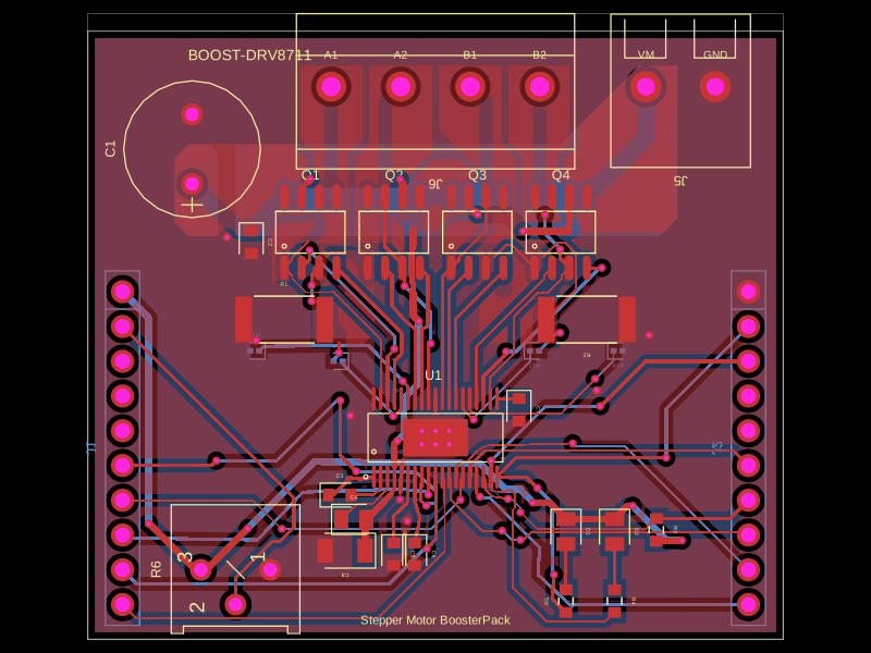 More from this authortscircuit/boostersThis code defines PCB schematics, footprints, and 3D CAD models for various integrated circuits, connectors, sensors, and electronic components used in TI booster packs and modules.
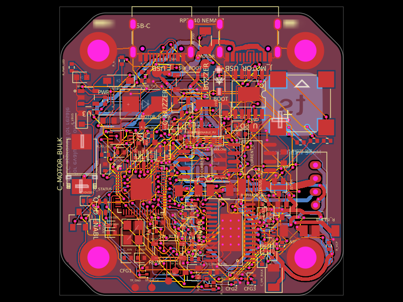 Similar packageimrishabh18/rp2040-motor-controllerA four-layer RP2040-based NEMA17 stepper controller with USB-C power/data, CH224K USB-PD negotiation, DRV8825 dual H-bridge drive, current/temperature telemetry, RGB status LED, buzzer alarm, QSPI flash, and optional AS5600 encoder.
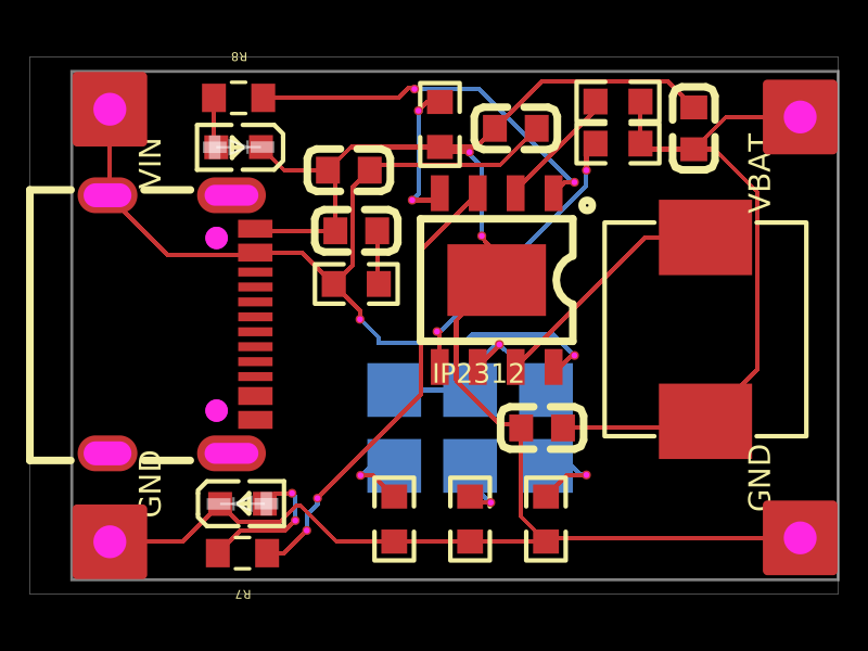 Discover something newkrishnax12/ip2312-fast-charging-moduleThis design implements a compact PCB with a USB-C input port, IP2312 battery charger IC, associated passive components (capacitors, resistors, inductor), output terminals for BAT and GND, and status indicator LEDs, facilitating fast lithium battery charging.