tscircuit/boosters
This code defines PCB schematics, footprints, and 3D CAD models for various integrated circuits, connectors, sensors, and electronic components used in TI booster packs and modules.
- Version
- 0.1.19
- License
- unset
- Stars
- 0
boostxl-tlv8544pir/README.md
# BOOSTXL-TLV8544PIR tscircuit reconstruction

This is an engineering reconstruction of Texas Instruments' `BOOSTXL-TLV8544PIR` PIR motion-detector BoosterPack.

## Current status

- The complete 70-component, 40-net design is written directly in `index.circuit.tsx`. There is no secondary board file.
- Resistors and capacitors use native tscircuit elements. Every other populated electronic part is instantiated from an exact JLCPCB import: J1-J4, U1-U3, A1, D1-D5, L1/L2, and TP1/TP2.
- TI's two-page schematic was transcribed from SNOU148A Figures 27 and 28 and laid out as two native tscircuit sheets with five native schematic sections. Compact named traces keep every net label at eight characters or fewer and clear of the section dividers. U1 is projected as U1A-U1D op-amp units, the LaunchPad connectors/LEDs sit below the PIR signal chain, and the power/current-monitor circuit occupies sheet 2. C22 is correctly placed across R21, and NT1/NT2/NT3 preserve TI's rail split.
- The unpublished original U3 identity is not guessed. `TLV333IDBVR` is explicitly selected as a qualified, orderable unity-gain-buffer substitute and uses its exact JLCPCB C473369 import with corrected data-sheet pin labels.
- The obsolete SMT PIR is replaced by Murata `IRA-S210ST01` (JLCPCB C152563), using its exact imported three-lead through-hole footprint. The matching lens is Murata `IML-0688`.
- Every populated electrical component has a manufacturer part number and a JLCPCB/LCSC part number. J3/J4 use imported DEALON DZ254S-11-02-48 C5160785 vertical SMT headers, and TP1/TP2 use imported Keystone 5001 C238122.
- The reconstructed board is 60.96 mm × 50.8 mm. Its bottom-mounted J1/J2 female sockets mate downward into the LaunchPad; their 43.18-mm center spacing (45.72 mm between outer header columns), asymmetric overhang, three holes, and outline are inferred from TI's scale image and BoosterPack grid because TI did not publish native PCB CAD for this board.
- The local v6 router completes 131 PCB traces with 117 vias, 0.30-mm via drills, 0.45-mm via pads, and a bottom GND pour. The circuit JSON contains zero placement, routing, or connectivity errors.

## Release status

This is an **orderable prototype release candidate**, not a production-proven clone. The electrical values, topology, MPNs, footprints, and supplier IDs are traceable. Before paying for assembly, confirm the reconstructed outline/header/hole/lens geometry against the intended LaunchPad; the IRA-S210 substitution and lens housing require first-article qualification.

- Original engineering source: <https://github.com/Abse2001/BOOSTXL-TLV8544PIR-tscircuit>
- Published tscircuit package: <https://tscircuit.com/abse/boostxl-tlv8544pir> (`1.0.13`)

This BoosterPack directory intentionally follows the source-only layout used by the other boards in this repository: the circuit entrypoint and TypeScript component imports are tracked, while generated build/manufacturing outputs and downloaded model files are not.

## Commands

```sh
bun install
bun run typecheck
bun run build
bun run dev
```

Run these commands from the repository root. Build output is written under `dist/`.
Related Packages
 More from this authortscircuit/autorouting-dataset-01This code manages the hardware and electronic components for circuit design and PCB layout, defining components like resistors, capacitors, transistors, connectors, and footprints, and providing tools for component placement, PCB topology, and electrical connections.
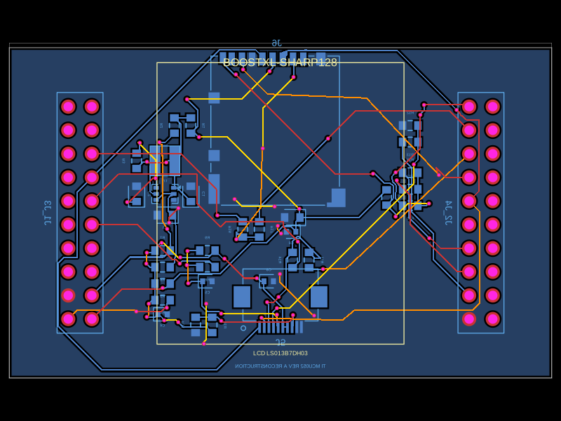 Similar packageabse/boostxl-sharp128This code defines a printed circuit board (PCB) with various surface-mount resistors, capacitors, inductors, and integrated circuits, including power management components and interface connectors, for a TI-based LCD and microSD module using 0603 and other package types.