tscircuit/boosters
This code defines PCB schematics, footprints, and 3D CAD models for various integrated circuits, connectors, sensors, and electronic components used in TI booster packs and modules.
- Version
- 0.1.19
- License
- unset
- Stars
- 0
boostxl-rs232/README.md
# BOOSTXL-RS232 serial-interface BoosterPack

Native tscircuit reconstruction of Texas Instruments' BOOSTXL-RS232 dual-channel RS-232 BoosterPack. The design follows TI user guide SLLU250 and its schematic, with a TRS3122E transceiver, DB9 connector, signal-status LEDs, selectable 1.8 V or 3.3 V logic supply, and configurable LaunchPad GPIO routing.

The schematic is divided into three functional sheets:

- **RS-232 Transceiver and Power** — DB9 interface, TRS3122E, charge pump, logic-voltage regulator, supply selection, and support components.
- **Status LEDs and Test Header** — power indicator, RX/TX/RTS/CTS activity indicators, and the accessible RS-232 signal header.
- **Interface and Signal Routing** — BoosterPack headers, GPIO-selection banks, and FORCEON/FORCEOFF/INVALID assignment header.

The PCB preserves the BoosterPack outline, mounting holes, component placement, LaunchPad headers, test and configuration headers, and two-layer construction. RX, TX, RTS, and CTS can be routed through the on-board selection headers, while FORCEON, FORCEOFF, and INVALID remain accessible for transceiver control and monitoring.

This directory follows the source-only layout used by the other boards in this repository: the circuit entrypoint, flat TypeScript component imports, documentation, and canonical snapshots are tracked. Generated manufacturing files, reference archives, caches, dependencies, and downloaded CAD models are not stored here.

## Checks

Run from the repository root:

```sh
bun install
bun run typecheck
bun run build
bunx tsci check shorts boostxl-rs232/index.circuit.tsx --mode gerber --layer all
bunx tsci snapshot boostxl-rs232/index.circuit.tsx --3d --disable-parts-engine
```

## Source authority and release status

- Connectivity, component values, part identities, and designators follow TI's official BOOSTXL-RS232 schematic and BOM.
- Board dimensions, mounting holes, placement, connector orientation, and the two-layer stack follow the reference board documentation and photographs.
- The design is suitable only for a small, current-limited first-article prototype order until connector fit, supply selection, RS-232 signaling, status indicators, and LaunchPad GPIO routing are verified on hardware.
- Passing automated checks proves internal consistency and absence of detected copper shorts; it does not replace fabrication review or bench validation.

Official product page: <https://www.ti.com/tool/BOOSTXL-RS232>

Official user guide: <https://www.ti.com/lit/ug/sllu250/sllu250.pdf>
Related Packages
 More from this authortscircuit/autorouting-dataset-01This code manages the hardware and electronic components for circuit design and PCB layout, defining components like resistors, capacitors, transistors, connectors, and footprints, and providing tools for component placement, PCB topology, and electrical connections.
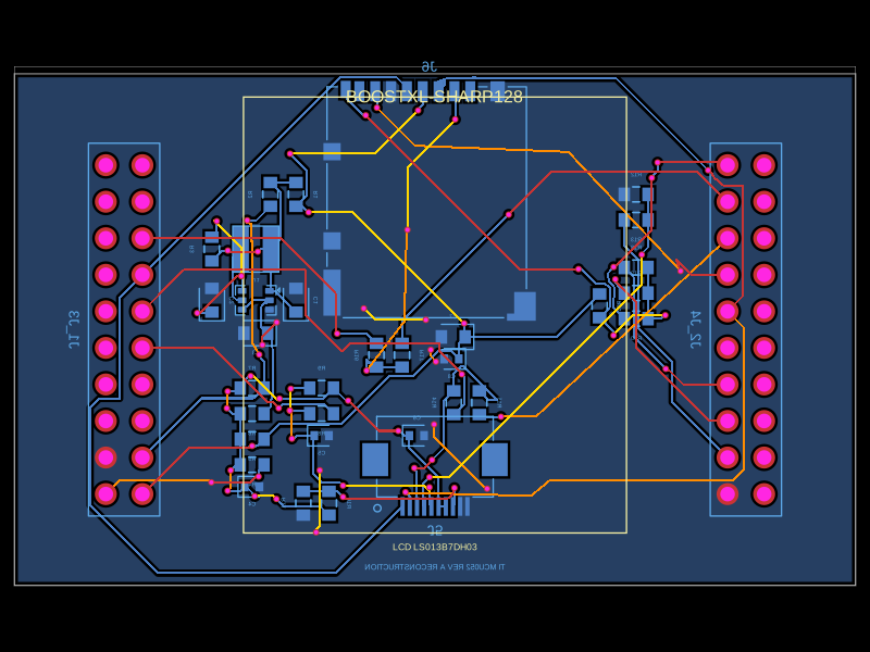 Similar packageabse/boostxl-sharp128This code defines a printed circuit board (PCB) with various surface-mount resistors, capacitors, inductors, and integrated circuits, including power management components and interface connectors, for a TI-based LCD and microSD module using 0603 and other package types.