tscircuit/boosters
This code defines PCB schematics, footprints, and 3D CAD models for various integrated circuits, connectors, sensors, and electronic components used in TI booster packs and modules.
- Version
- 0.1.19
- License
- unset
- Stars
- 0
boostxl-edumkii/README.md
# Educational BoosterPack TS

A two-layer tscircuit board inspired by TI's BOOSTXL-EDUMKII Educational BoosterPack. It retains the wide, rounded BoosterPack form factor and combines a display, environmental and motion sensors, user controls, audio I/O, lighting, and a servo connector on one LaunchPad XL-compatible board.

This is an original, modernized reference design. It is not a pin-for-pin manufacturing copy of the TI board.

## Board overview

- 127 mm × 55.88 mm pill-shaped PCB, 1.6 mm thick, two copper layers
- Four bottom-mounted 1×10 female headers in the standard 40-pin BoosterPack XL arrangement
- 1.8-inch ST7735-style SPI TFT interface
- OPT3001 ambient light sensor with interrupt output
- TMP117 digital temperature sensor with interrupt output
- LIS3DH digital three-axis accelerometer with interrupt output
- Two-axis joystick with select switch
- Two pushbuttons and paired gator/touch pads
- Electret microphone with an OPA344 analog preamplifier
- Common-anode RGB LED with transistor drivers
- 5 V buzzer with transistor driver and flyback diode
- Three-pin 5 V servo connector
- 3.3 V and 5 V power indicators
- Bottom-layer ground pour

The sensor choices are modernized relative to the original board: TMP117 replaces the original TMP006 temperature sensor, and LIS3DH replaces the original analog accelerometer.

## 3D model sources

The 3D assembly uses imported JLCPCB/LCSC CAD records for every placed package. Important mechanical matches include C37323742 for the analog joystick, C84931 for the 12 mm buttons, C530035 for the 9.7 mm electret microphone, C96093 for the 12 mm buzzer, C5345899 for the PLCC4 RGB LED, C2897411 for the 2×10 female headers, and C49257 for the servo header. Package-compatible JLC models are also assigned to every resistor, capacitor, transistor, signal diode, and power LED.

The legacy Crystalfontz TFT panel is not present in JLCPCB's current catalog. Its original SFV10R-2STE1HLF FFC connector was imported as C3195321, and the preview uses an inline dimensionally matched panel model so the display assembly remains visible without relying on unsupported OBJ/MTL assets.

## Schematic organization

The schematic is divided across three sheets, with generous spacing between the functional sections on each sheet:

1. Interface, Display & Controls
   - LaunchPad Interface
   - SPI TFT Display
   - Joystick & Buttons
2. Sensors & Microphone
   - Environmental & Motion Sensors
   - Microphone Front End
3. Outputs, Expansion & Power
   - RGB LED & Buzzer Drivers
   - Servo & Clip Expansion
   - Power Indicators

Connections between sections and sheets use explicit electrical net names such as `I2C_SCL`, `LCD_MOSI`, `JOY_X`, and `MIC_IN`. Internal nodes also have semantic names including `MIC_BIAS`, `MIC_FB`, `RGB_RED_SINK`, and `BUZZER_BASE`; generated component-selector paths are not used as visible net labels.

## LaunchPad header assignment

| Header pin | Signal | Function |
|---|---|---|
| J1.1 | 3V3 | Logic supply |
| J1.2 | JOY_X | Joystick X analog output |
| J1.5 | JOY_SEL | Joystick select switch |
| J1.6 | MIC_IN | Microphone amplifier output |
| J1.7 | LCD_SCLK | TFT SPI clock |
| J1.8 | LIGHT_INT | OPT3001 interrupt |
| J1.9 | I2C_SCL | Shared sensor I2C clock |
| J1.10 | I2C_SDA | Shared sensor I2C data |
| J2.11 | TEMP_INT | TMP117 interrupt |
| J2.13 | LCD_CS | TFT chip select |
| J2.15 | LCD_MOSI | TFT SPI data |
| J2.17 | LCD_RST | TFT reset |
| J2.19 | SERVO_PWM | Servo control |
| J2.20 | GND | Ground |
| J3.21 | 5V | Peripheral supply |
| J3.22 | GND | Ground |
| J3.25 | ACC_INT | LIS3DH interrupt |
| J3.26 | JOY_Y | Joystick Y analog output |
| J4.31 | LCD_DC | TFT data/command |
| J4.32 | BTN2 | Pushbutton 2 |
| J4.33 | BTN1 | Pushbutton 1 |
| J4.34 | GATOR | Gator/touch input |
| J4.37 | RGB_B | Blue LED channel |
| J4.38 | RGB_G | Green LED channel |
| J4.39 | RGB_R / LCD_BL | Red LED channel and TFT backlight |
| J4.40 | BUZZER | Buzzer control |

Unused header pins are explicitly marked as unconnected in the tscircuit source.

## Build

Prerequisites: Bun and a current Node.js runtime.

```sh
bun install
bun run typecheck
bun run build
```

Run these commands from the repository root. The build emits `circuit.json`, `pcb.svg`, and schematic SVG output under `dist/boostxl-edumkii/`. The Circuit JSON contains three schematic sheets with eight named functional sections.

The verified build runs the placement, routing, netlist, and pin-specification checks without bypass flags. It currently reports supplier-footprint mismatch warnings for the custom header and LED footprints, and the automatic router can produce tight via-to-pad clearance diagnostics that should be reviewed before fabrication. Narrow explicit courtyards preserve the required 2.54 mm spacing between adjacent BoosterPack header rows, circular courtyards reserve the full joystick, microphone, and buzzer bodies, rectangular courtyards protect both pushbutton envelopes, and separated clip-pad annuli satisfy copper clearance rules.

The root build allows up to five minutes for a cache-free autoroute of this dense two-layer board. Subsequent builds can reuse tscircuit's route cache and typically complete much faster.

## Before fabrication

This is a prototype/reference design, not a production-ready fabrication release.

- Confirm the exact parts and footprints for display `U5`, `SW1`, `SW2`, microphone `U7`, RGB LED `U8`, and buzzer `U9`. Joystick `U6` uses the complete imported JLCPCB C37323742 footprint and CAD model. Verify every selected production part against its manufacturer drawing.
- Confirm the actual TFT module pin order; ST7735 modules are not universally pin-compatible.
- Check the selected servo and buzzer current against the LaunchPad 5 V source and USB power budget. Use external power if required.
- Validate connector stack height, joystick/button ergonomics, clearances, creepage, ESD protection, emissions, and regulatory requirements for the final enclosure and application.
- Generate fabrication outputs only after a footprint-by-footprint review against manufacturer drawings and an independent electrical review.

## References

- [TI BOOSTXL-EDUMKII product page](https://www.ti.com/tool/BOOSTXL-EDUMKII)
- [TI BOOSTXL-EDUMKII user guide](https://www.ti.com/lit/ug/slau599b/slau599b.pdf)

TI's published board dimensions, connector placement, and documented signal functions were used as interoperability references. TI trademarks remain the property of Texas Instruments.
Related Packages
 More from this authortscircuit/autorouting-dataset-01This code manages the hardware and electronic components for circuit design and PCB layout, defining components like resistors, capacitors, transistors, connectors, and footprints, and providing tools for component placement, PCB topology, and electrical connections.
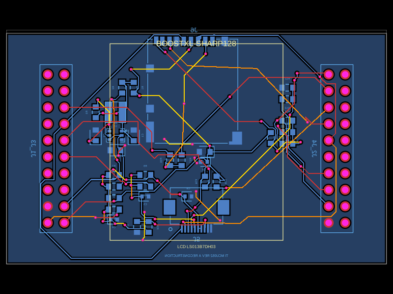 Similar packageabse/boostxl-sharp128This code defines a printed circuit board (PCB) with various surface-mount resistors, capacitors, inductors, and integrated circuits, including power management components and interface connectors, for a TI-based LCD and microSD module using 0603 and other package types.