techmannih/usbc-charger
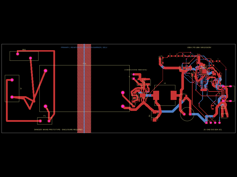
This code defines a detailed electronic hardware design for an 85-265VAC to USB-C PD 18W wall charger, including the schematic layout and physical component placements such as connectors, filtering inductors, capacitors, resistors, protection diodes, and an isolated power module, all integrated with 3D models and mechanical enclosures.
- Version
- 1.0.7
- License
- unset
- Stars
- 0
LAB_VALIDATION_PLAN.md
PCB

Schematic

# Lab validation plan

All mains tests must be performed by qualified personnel using an accredited laboratory or an appropriately equipped safety lab. This document defines evidence to obtain; it is not an instruction for unprotected bench testing.

## 1. Sample and document control

- Record PCB revision, Gerber hash, exact BOM/lot codes, AC/DC module date code, the full U2 top marking and confirmation that it is the standard non-PPS IP6520, enclosure resin lot, cord/plug and label revision.
- Compare samples against schematic, PCB, critical-component list and mechanical drawings.
- Photograph the unopened product, internal construction, spacings, wiring, anchorage and markings.

## 2. Construction and safety review

- Confirm Class II construction, insulation system, primary-to-SELV creepage/clearance, PCB material group, pollution degree and altitude assumptions.
- Measure the real assembled spacings, including component bodies, leads, solder fillets, mounting hardware, enclosure ribs and connector openings—not only nominal CAD separation.
- Evaluate fuse breaking capacity and coordination, MOV failure/thermal risk, X2 capacitor and bleeder ratings, internal wire ratings and polarity.
- Perform accessibility/probe, cord anchorage, pull/twist, fastener retention, impact/drop and enclosure material/heat assessments required by the applicable standard.

## 3. Electrical safety and performance

- Input current/power, no-load consumption, end-to-end efficiency and output regulation across declared input limits and every supported PDO.
- Dielectric-strength, insulation-resistance and touch/leakage-current tests using lab-selected levels and sequences.
- Output current limit, short circuit, overload, repeated startup and recovery.
- Verify 5 V default behavior before PD negotiation and all supported 5 V, 9 V and 12 V transitions under static and dynamic load.
- Verify that Source_Capabilities contains only the 5 V / 3 A, 9 V / 2 A, and 12 V / 1.5 A fixed-supply PDOs, with no PPS APDO, and that unsupported requests are rejected safely.
- Characterize 12 V / 1.5 A specifically with U2 supplied from the real 15 V module rail at its measured minimum and maximum voltage. Include startup, load steps, cable drop, dropout/regulation margin and protection behavior because the datasheet's 12 V electrical-characteristic point uses a 24 V input.
- Test cable attach/detach, cable orientation, unsupported requests, brownout/restart and representative phones/cables in addition to protocol-analyzer tests.

## 4. Thermal and abnormal conditions

- Temperature rise at low and high declared mains voltage, no load, typical load and continuous 18 W at both 9 V / 2 A and 12 V / 1.5 A in the final closed enclosure.
- Demonstrate that U1 remains within its 15 V / 1.333 A output rating and temperature derating limits while supplying converter losses at 18 W USB output; the nameplate ratings alone are not evidence of adequate margin.
- Record ambient, stabilization criterion and temperatures of U1, U2, L1, fuse, MOV, NTC, C7, connectors, PCB, internal wiring and enclosure touch surfaces.
- Apply the standard's relevant single-fault/abnormal conditions, blocked ventilation, output short/overload and component fault simulations.
- Inspect for charring, insulation damage, displaced parts, loss of protective function or unsafe restart after each test.

## 5. EMC, immunity and port robustness

- Conducted and radiated emissions on representative mains leads, loads, USB cables and enclosure configuration.
- Applicable ESD, electrical fast transient, surge, RF immunity, voltage dips/interruptions and magnetic-field tests selected by the lab for the destination market.
- Confirm fuse/MOV coordination after surge sequences and inspect protective parts for degradation.
- Repeat essential output and PD behavior after immunity exposure.

## 6. USB-IF program

- Use an authorized USB-IF independent test lab and the current applicable Type-C and USB-PD compliance test specifications.
- Exercise every supported PDO, source-capability message, role behavior, CC orientation, error recovery and relevant USB 2.0 path requirement.
- Resolve all waivers/issues, obtain the TID/listing and approve logo/claim usage before packaging release.

## 7. Production end-of-line controls

The accredited lab and safety engineer should approve limits and fixtures for:

- visual/traceability and critical-component verification;
- dielectric/leakage or the permitted production equivalent;
- output voltage/current-limit and PD handshake checks;
- insulation/fixture interlocks, calibration, failure segregation and retained records.

## Release gate

Release requires passing reports tied to the final hardware/enclosure revision, closure of every nonconformity, approved product markings/instructions and written disposition for all deviations. A clean CAD build or successful bench charge does not satisfy this gate.