techmannih/usbc-charger
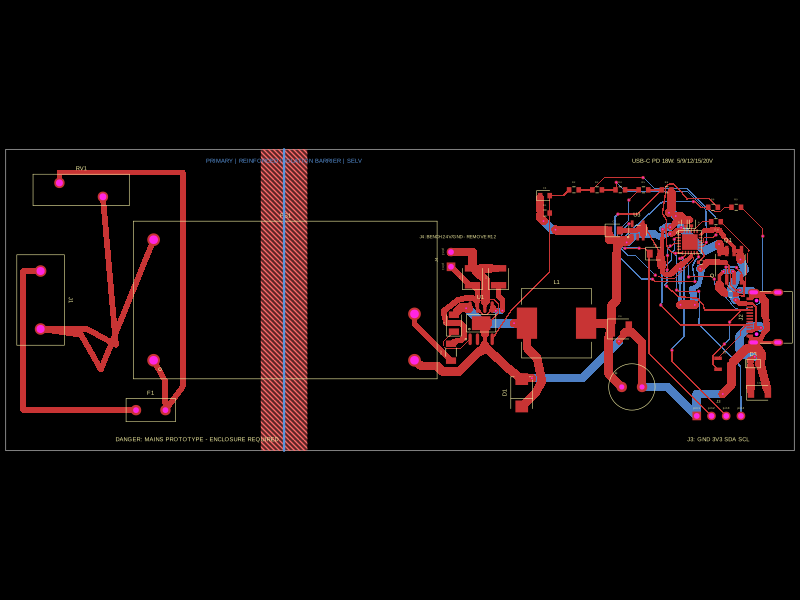
This code defines a detailed electronic hardware design for an 85-265VAC to USB-C PD 18W wall charger, including the schematic layout and physical component placements such as connectors, filtering inductors, capacitors, resistors, protection diodes, and an isolated power module, all integrated with 3D models and mechanical enclosures.
- Version
- 1.0.7
- License
- unset
- Stars
- 0
ENCLOSURE_REQUIREMENTS.md
PCB

Schematic

# Production enclosure requirements

The `enclosure.fdm.box` in the circuit is a 116 × 66 × 42 mm fit-check shell. It is suitable for checking connector alignment and board volume only. Do not use a hobby FDM print as the consumer mains enclosure.

The production mechanical design must be reviewed with the safety lab and should include:

- a certified/traceable flame-retardant insulating resin and process appropriate to the applicable standard, with material documentation retained per production lot;
- no user-accessible primary conductor, terminal, screw, solder joint or mounting hardware under accessibility probes and expected deformation;
- a rated two-core mains lead and plug for the destination market, with double-insulated internal wiring and a listed cable gland/strain relief sized to the real cord;
- independent cord anchorage so a pull or twist cannot load J1 or reduce primary-to-SELV spacing;
- insulating ribs/barriers and standoff geometry that preserve required creepage/clearance after assembly tolerances, solder protrusion, impact and heat;
- captive/secure board retention using the four 3.2 mm non-plated holes without conductive hardware bridging insulation zones;
- a USB-C opening that cannot expose internal live parts and does not mechanically overload J2;
- ventilation only if the lab accepts it; openings must still pass accessibility and fire-containment requirements;
- tamper-resistant closure, adequate impact strength and no service access for ordinary users;
- permanent external ratings, model/serial traceability, indoor-use/safety markings and certification identifiers only after authorization.

## Mechanical release checks

- Import the actual PCB STEP output and exact bought-out connector/cord models into production CAD.
- Apply dimensional, molding/shrink and assembly tolerance stacks to apertures, standoffs and insulation barriers.
- Verify assembly sequence, no pinched wires, strain-relief engagement, fastener torque and repeatable connector location.
- Conduct thermal testing in the real color, resin, wall thickness and closed configuration; the fit-check shell is not a thermal surrogate.
- Freeze the enclosure drawing, resin grade, molder/process and cord assembly as certification-controlled items.