techmannih/usbc-charger
This code defines a detailed electronic hardware design for an 85-265VAC to USB-C PD 18W wall charger, including the schematic layout and physical component placements such as connectors, filtering inductors, capacitors, resistors, protection diodes, and an isolated power module, all integrated with 3D models and mechanical enclosures.
- Version
- 1.0.7
- License
- unset
- Stars
- 0
COMPLIANCE_PLAN.md
PCB

Schematic

# Compliance plan

Status: engineering-validation design; no certification, registration, licence, TID or logo authorization has been obtained.

This plan must be frozen against the exact PCB revision, BOM, firmware/silicon revision, mains cord/plug and final enclosure submitted to the labs. A change to any safety-critical item can require review or retest.

## Intended product definition

- External Class II power adaptor for IT/consumer equipment.
- Label input: 100–240 VAC, 50/60 Hz. The AC/DC module's 85–265 VAC figure is an operating range, not the proposed consumer label range.
- USB-C source PDOs: 5 V/3 A, 9 V/2 A and 12 V/1.5 A; 18 W maximum; exact standard IP6520 non-PPS variant.
- No protective-earth connection.
- Final construction: closed, touch-safe, flame-retardant enclosure with a rated mains cord/plug and strain relief.

## Workstream matrix

| Workstream | Design evidence available | Required independent evidence before sale |
| --- | --- | --- |
| India electrical safety | Isolated module architecture, fused/protected input, primary/SELV keepout, controlled BOM | BIS-recognized lab report and registration for the final adaptor under the classification/standard confirmed by BIS; construction, dielectric, temperature and abnormal-condition results |
| International electrical safety | Hazard-based design provisions and component documentation | Accredited evaluation to the applicable market edition, commonly IEC 62368-1 or its national adoption; national deviations and marking review |
| USB Type-C/PD | Standard non-PPS IP6520 reference topology and fixed-supply PDO intent | USB-IF-authorized lab execution of every applicable Type-C and PD CTS section; valid TID/listing before using certified USB claims or logos |
| EMC/immunity | CMC, X2 capacitor, local bypassing, short power loops and port ESD parts | Conducted/radiated emissions and applicable ESD, EFT, surge, dips/interruptions and immunity tests on the final closed product |
| Energy efficiency | Low-power topology selected | Applicable market efficiency/no-load measurements and declarations for external power supplies |
| Materials/mechanics | Mounting holes and fit-check enclosure model | Resin flammability evidence, touch-access/probe tests, impact/drop, cord anchorage, torque, heat/ball-pressure and enclosure construction review |
| Production conformity | Exact MPNs and supplier numbers recorded | Approved-vendor list, incoming inspection, traceability, calibrated end-of-line tests and controlled change process |

## India submission package

Prepare at minimum:

- final schematic, PCB artwork/stack-up, critical-component list and BOM;
- component certificates/datasheets for the AC/DC module, fuse, MOV, X2 capacitor, PCB laminate, enclosure resin, connector and mains lead/plug;
- photographs and construction drawings showing insulation barriers, spacings, internal wiring, strain relief and markings;
- product label artwork, model/series declaration and user safety instructions;
- risk assessment, abnormal-condition rationale and production test procedure;
- samples that exactly match the declared PCB, enclosure and critical BOM.

India's current BIS material lists “Power Adaptors for IT Equipments” under IS 13252 (Part 1):2010. The published uniform test report references amendments A1:2013 and A2:2015. The applicant/lab must verify the current classification and amendments at submission time; do not print a BIS standard mark or registration number before grant.

## Change control

Treat these as certification-affecting changes: AC/DC module source or construction, PCB layout in the mains/isolation region, fuse or MOV rating, X/Y safety capacitor, enclosure material/wall geometry, mains cord/plug/strain relief, USB-PD buck SoC variant or supported PDOs. Other IP6520 family variants are not approved substitutions for the standard non-PPS `IP6520`. Record the rationale and obtain lab/certification-body disposition before production.

## Authoritative starting points

- [BIS Scheme II compulsory-registration products](https://www.bis.gov.in/product-certification/products-under-compulsory-certification/scheme-ii-registration-scheme/)
- [BIS power-adaptor uniform test report](https://www.bis.gov.in/PDF/UTRFs/FINALIZED_TRF_IS_13252_A1_A2_Power_Adaptor_for_IT_Equipment_V1_3.pdf)
- [MeitY series guidelines](https://www.meity.gov.in/sites/upload_files/dit/files/Revised_SeriesGuideline.pdf)
- [IEC 62368-1:2023 publication](https://webstore.iec.ch/en/publication/20471)
- [USB-IF USB Type-C/PD compliance overview](https://www.usb.org/usbc)
- [USB-IF compliance program](https://www.usb.org/compliance)
- [USB Power Delivery Compliance Test Specification](https://www.usb.org/document-library/usb-power-delivery-compliance-test-specification-0)
Related Packages
 More from this authortechmannih/testsCreates a 10mm x 10mm circuit board featuring an axial battery component labeled U1 at the origin.
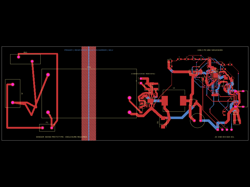 Similar packageseveibar/usbc-pd-chargerThis code defines and assembles a hardware schematic of an 18W USB-C PD wall charger with mains input, protection, high-voltage isolation, a DC buck converter with switching regulator, filtering, and USB-C output with ESD protection.
 Discover something newabse/boostxl-uln2003This code defines a React component that models a through-hole or surface-mount LED with specified pin labels, footprint, silkscreen, and 3D CAD model for PCB layout.