techmannih/nema34-mounted-stepper-controller
A USB-C PD-powered RP2040 motor controller with protected 48 V power, DRV8262 dual-bridge drive for a NEMA34 motor, regenerative-braking resistor, isolated sensing, hardware interlocks, and telemetry/status interfaces.
- Version
- 0.3.113
- License
- unset
- Stars
- 1
system-overview.tsx
import { systemblock } from "system-block-core"
const Block = systemblock.component

/** Review interfaces only; electrical connections remain in index.circuit.tsx. */
export const SystemOverview = () => (
  <>
    <systemblock.page name="system-overview" displayName="Motor Controller Architecture" direction="right"
      description="Orange dashed arrows carry power; blue arrows carry signals. Read the PD input, motor supply and motor drive first. Details are on pages 2–4.">
      <Block name="pd" displayName="J1 / USB-C PD EPR"
          description={"U1 + U2 · 48 V / 5 A request"}
          pcbComponentNames={["J1", "U1", "U2", "U3", "U36"]} />
      <Block name="data" displayName="J10 / USB data"
          description={"5 V input · diagnostics + MCU power"}
          pcbComponentNames={["J10", "U28", "U25"]} />
      <Block name="control" displayName="U16 / RP2040"
          description={"U17 flash · motion locks enabled"}
          pcbComponentNames={["U16", "U17", "U39", "U40"]} />
      <systemblock.group name="power-stage" displayName="Protected motor power + regenerative braking">
        <Block name="bus" displayName="U6 / Protected motor supply"
          description={"eFuse + Q4/Q5 reverse blocking"}
          pcbComponentNames={["Q4", "Q5", "U6"]} />
        <Block name="driver" displayName="U7 / DRV8262DDVR"
          description={"Integrated bridges + current control"}
          pcbComponentName="U7" />
        <Block name="brake" displayName="J3 / External brake resistor"
          description={"Q16 · ~52 V clamp · rating provisional"}
          pcbComponentNames={["U12", "U13", "U15", "U34", "Q16", "J3"]} />
      </systemblock.group>
      <Block name="motor" displayName="J2 / NEMA34 motor"
          description={"WAGO · 34HS31-6004S1"}
          pcbComponentName="J2" />
      <systemblock.connection from="pd" to="bus" kind="power" label="PD input" />
      <systemblock.connection from="bus" to="driver" kind="power" direction="both" label="Motor bus / regen" />
      <systemblock.connection from="driver" to="motor" kind="power" direction="both" label="Two windings" />
      <systemblock.connection name="data-power" from="data" to="control" kind="power" label="Via LDO (p.2)" />
      <systemblock.connection name="data-link" from="data" to="control" direction="both" label="USB" />
      <systemblock.connection from="control" to="driver" label="PH/EN + current references" />
      <systemblock.connection from="bus" to="brake" kind="power" label="Bus energy" />
    </systemblock.page>

    <systemblock.page name="logic-power" displayName="Power Distribution" direction="right"
      description="The MCU requires DATA power. U39/U40 isolate PD-powered inputs. The PD and DATA inputs are not joined. U5/U22/U34 are step-down bucks, not buck-boosts. VMOTOR backup keeps the independent brake powered during PD loss.">
      <systemblock.group name="sources" displayName="3.3 V sources">
        <Block name="pd-buck" displayName="PD → 3.3 V"
          description={"U5 + L1 · PD input buck"}
          pcbComponentNames={["J1", "U5", "L1"]} />
        <Block name="backup" displayName="Motor bus → 3.3 V"
          description={"U22 + L2 · backup during PD loss"}
          pcbComponentNames={["U6", "U22", "L2"]} />
        <Block name="data" displayName="DATA → 3.3 V"
          description={"U28 current limit + U25 LDO"}
          pcbComponentNames={["J10", "U28", "U25"]} />
      </systemblock.group>
      <systemblock.group name="board-domain" displayName="Board supply">
        <Block name="board-or" displayName="Board supply selection"
          description={"U23 / U24 · reverse-blocking selection"}
          pcbComponentNames={["U23", "U24"]} />
        <Block name="sensing" displayName="Board logic"
          description={"Sensors, run gates and comparators"}
          pcbComponentNames={["U12", "U13", "U14", "U29", "U30", "U38"]} />
      </systemblock.group>
      <systemblock.group name="mcu-domain" displayName="MCU supply">
        <Block name="mcu-or" displayName="DATA-only reverse blocker"
          description={"U27 · no PD-to-MCU supply"}
          pcbComponentName="U27" />
        <Block name="mcu" displayName="MCU + flash"
          description={"U16 + U17 · U39/U40 I/O isolation"}
          pcbComponentNames={["U16", "U17", "U39", "U40"]} />
        <Block name="sensor-power" displayName="Switched sensor / driver logic"
          description={"U41 · off at reset / USB suspend"}
          pcbComponentNames={["U41", "U31", "U32", "U18", "U42", "U7"]} />
      </systemblock.group>
      <systemblock.group name="brake-domain" displayName="Brake gate supply">
        <Block name="brake-buck" displayName="Motor bus → 12 V"
          description={"U34 + L3 · buck from VMOTOR"}
          pcbComponentNames={["U34", "L3"]} />
        <Block name="brake-driver" displayName="Brake gate driver"
          description={"U15 drives Q16 · independent of MCU"}
          pcbComponentNames={["U15", "Q16"]} />
      </systemblock.group>
      <systemblock.connection from="pd-buck" to="board-or" kind="power" label="3.3 V" />
      <systemblock.connection from="backup" to="board-or" kind="power" label="Backup 3.3 V" />
      <systemblock.connection from="data" to="mcu-or" kind="power" label="USB 3.3 V" />
      <systemblock.connection from="mcu-or" to="mcu" kind="power" label="MCU 3.3 V" />
      <systemblock.connection from="mcu-or" to="sensor-power" kind="power" label="Via U41 / 3.3 V" />
      <systemblock.connection from="mcu" to="sensor-power" label="SENSE_EN" />
      <systemblock.connection from="board-or" to="sensing" kind="power" label="V3V3" />
      <systemblock.connection from="brake-buck" to="brake-driver" kind="power" label="12 V" />
    </systemblock.page>

    <systemblock.page name="protection" displayName="Protection and Interlocks" direction="right"
      description="Power permission and driver enable are separate gates. The brake responds to bus voltage independently of firmware. Nominal thresholds still need bench verification.">
      <systemblock.group name="motion-permission" displayName="Power permission and motor enable">
        <Block name="pd" displayName="PD path ready"
          description={"U2 status via Q2 / Q3"}
          pcbComponentNames={["U2", "Q2", "Q3"]} />
        <Block name="permit" displayName="Power gate · U4"
          description={"PD_PATH_OK AND POWER_PERMIT"}
          pcbComponentName="U4" />
        <Block name="efuse" displayName="Input protection · U6"
          description={"Current / voltage limits + MOTOR_PG"}
          pcbComponentName="U6" />

        <Block name="mcu" displayName="Firmware permission"
          description={"U16 · contract, sensors, qualification"}
          pcbComponentName="U16" />
        <Block name="run" displayName="Run gates · U10/11/33"
          description={"MCU_RUN AND MOTOR_PG AND\nVMOTOR_OK AND TEMP_OK"}
          pcbComponentNames={["U10", "U11", "U33"]} />
        <Block name="driver" displayName="Driver enable · U7"
          description={"RUN_SAFE → nSLEEP · low disables bridges"}
          pcbComponentName="U7" />

        <Block name="limits" displayName="Hardware limits"
          description={"U12/U14 voltage limit + U29 temperature"}
          pcbComponentNames={["U12", "U14", "U29"]} />
      </systemblock.group>
      <systemblock.group name="independent-brake" displayName="Independent brake">
        <Block name="threshold" displayName="Brake threshold"
          description={"U12 / U13 · bus near 52 V"}
          pcbComponentNames={["U12", "U13"]} />
        <Block name="brake" displayName="Brake switch · J3"
          description={"U15 + Q16 · no MCU command needed"}
          pcbComponentNames={["U15", "Q16", "J3"]} />
      </systemblock.group>
      <systemblock.connection from="pd" to="permit" label="PD ready" />
      <systemblock.connection from="mcu" to="permit" label="POWER_PERMIT" />
      <systemblock.connection from="permit" to="efuse" label="EFUSE_EN" />
      <systemblock.connection from="efuse" to="run" label="MOTOR_PG" />
      <systemblock.connection from="mcu" to="run" label="MCU_RUN" />
      <systemblock.connection from="limits" to="run" label="Voltage + temp OK" />
      <systemblock.connection from="run" to="driver" label="RUN_SAFE" />
      <systemblock.connection from="threshold" to="brake" label="BRAKE_ON" />
    </systemblock.page>

    <systemblock.page name="control-telemetry" displayName="Control and Telemetry" direction="right"
      description="PD_READY is firmware-derived from the EPR contract and fresh U38 raw-voltage data. It is not the hardware eFuse MOTOR_PG. Optional encoder is telemetry only.">
      <systemblock.group name="sensing" displayName="Supply + motor sensing">
        <Block name="pd" displayName="PD contract"
          description={"U2 + U3 EEPROM + U36 isolation"}
          pcbComponentNames={["U2", "U3", "U36"]} />
        <Block name="voltage" displayName="Voltage / brake ADCs"
          description={"U38 raw PD · U30 VMOTOR / brake / IMON"}
          pcbComponentNames={["U38", "U30"]} />
        <Block name="feedback" displayName="Current + temperature"
          description={"U31/U32 current sense · U29 temperature"}
          pcbComponentNames={["U31", "U32", "R115", "R116", "U29"]} />
      </systemblock.group>
      <Block name="controls" displayName="Local buttons"
          description={"SW1 RESET · SW2 START/STOP"}
          pcbComponentNames={["SW1", "SW2"]} />
      <Block name="mcu" displayName="U16 / RP2040"
          description={"PD_READY = contract + fresh PD ADC"}
          pcbComponentName="U16" />
      <systemblock.group name="outputs" displayName="Motion + status interfaces">
        <Block name="driver" displayName="Motor driver · U7"
          description={"DRV8262 · nFAULT feedback · U42 current DAC"}
          pcbComponentName="U7" />
        <Block name="indicators" displayName="Status outputs"
          description={"U35/U37 · RGB LED + buzzer"}
          pcbComponentNames={["U35", "U37", "D16", "BZ1"]} />
        <Block name="encoder" displayName="Optional encoder · U18"
          description={"AS5600 · DNP, magnet unqualified"}
          pcbComponentName="U18" />
      </systemblock.group>
      <systemblock.connection from="pd" to="mcu" direction="both" label="PD I2C" />
      <systemblock.connection from="voltage" to="mcu" direction="both" label="PD I2C" />
      <systemblock.connection from="feedback" to="mcu" direction="both" label="ADC + PD I2C" />
      <systemblock.connection from="mcu" to="encoder" direction="both" label="Encoder I2C" />
      <systemblock.connection from="mcu" to="driver" direction="both" label="Control / feedback" />
      <systemblock.connection from="mcu" to="indicators" label="I2C + reset" />
      <systemblock.connection from="controls" to="mcu" label="RESET / button" />
    </systemblock.page>
  </>
)
Related Packages
 More from this authortechmannih/footprint-check-placementThis design features a 10mm x 10mm PCB with an integrated clock module chip connected to various digital, audio, and power nets, along with a nearby 100nF surface-mount capacitor for decoupling.
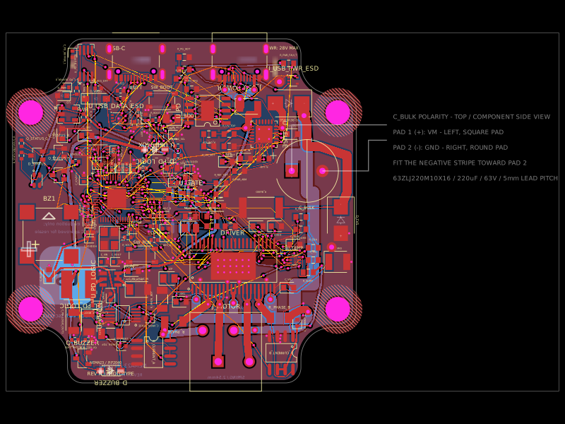 Similar packageimrishabh18/nema-23-stepper-controllerA 4-layer NEMA23 stepper-motor controller PCB combining an RP2040, DRV8462 dual-phase driver, USB-C Power Delivery/eFuse protection, current/voltage/temperature sensing, USB data multiplexing/ESD protection, optional AS5600 encoder, status LEDs, buzzer, and motor terminals.
 Discover something newabse/gameboy-advance