techmannih/nema34-mounted-stepper-controller
A USB-C PD-powered RP2040 motor controller with protected 48 V power, DRV8262 dual-bridge drive for a NEMA34 motor, regenerative-braking resistor, isolated sensing, hardware interlocks, and telemetry/status interfaces.
- Version
- 0.3.113
- License
- unset
- Stars
- 1
release/thermal-qualification.md
PCB

Schematic

# Driver, brake and installation qualification
**Installation design and post-assembly measurements.** The normal diagnostic image inhibits motor outputs; bounded test profiles are described in [commissioning](commissioning.md). The user confirmed that rear screw/thread measurements are not yet available. No physical tests, heatsink installation or supplier allocation have been performed.
## DRV8262DDV cooling
U7 is the top-cooled DDV package. [TI DRV8262, sections 5.4 and 8](https://www.ti.com/lit/ds/symlink/drv8262.pdf) specifies 0.7 °C/W junction-to-top-case thermal resistance. Use TIM between the exposed top and heatsink, mechanically support both ends, keep mounting load below TI's recommended 45 N, and ground or float the heatsink. TI recommends 2 oz top/bottom copper; our retained 1 oz stack has not demonstrated equivalent full-current performance. Changing copper weight requires a separate fabricator/impedance and geometry review.
A concrete reference is the **ATS-TI1OP-519-C1-R3** heatsink listed as MP1 in TI's earlier DRV8462VEVM MD041A(001) BOM. Provenance: [DRV8462VEVM](https://www.ti.com/tool/DRV8462VEVM) → [SLOR128 hardware archive](https://www.ti.com/lit/zip/SLOR128), `MD041A/MD041A(001) - DRV8462V EVM/MD041A(001)_BOM.xlsx`; downloaded archive SHA-256 `bf23445840bbe70e57c76adf6b565158af489283fcdf08e1c27a08bbafc8a495`. The manufacturer drawing is 78 × 36 × 35.6 mm with two M3 support positions. That envelope conflicts with the current board component layout, so this EVM sink is **rejected for direct installation**, not added to the fitted BOM.
TI names Ceramique and TIMTronics 413 as interface examples. [Arctic Silver Ceramique 2](https://arcticsilver.com/cmq2.html) is a currently documented TIM candidate; it is not a structural adhesive. Its application/bond-line behavior and interface resistance on the small DDV top must be established. Do not infer thermal resistance from compound identity alone.
### Compact cooling candidate and actual limitations
The part-level review is recorded in [cooling selection](../engineering/mechanical/cooling-selection.json). The downloaded [Same Sky HSB14-353518 drawing](https://www.sameskydevices.com/product/resource/hsb14-353518.pdf) defines a 35 × 35 × 18 mm, 15 g pin-fin sink with 1.5 mm base. Its natural-convection curve rises about 119.7 °C at 15 W; it cannot support our high-current thermal target passively. Its 200 LFM curve gives about 44.2 °C rise at 15 W, but this does not qualify a fan, restricted airflow, or a custom contact pedestal.
A plan-view candidate centered at `(22, -12)` mm clears the two larger bulk-capacitor envelopes in XY. This is **not an installed-fit result**: the DDV top-contact height, pedestal/spreading resistance, supports and actual component tolerances remain unresolved. Do not put this part into the production assembly simply because its plan view fits. No unsupported cooler is added to the motor model.
### Calculated cooling target
These are explicit engineering allocations for selecting/testing a cooling system, not guaranteed dissipation:
| Quantity | Basis / result |
|---|---|
| Proposed bench request | 0.8 A RMS maximum request, quantized nominal approximately 0.800 A; maximum 10 rpm, unloaded rotor |
| Two-phase conduction screen | `P = 2 × Irms² × (RHS + RLS)`; use existing audit resistance cases 0.100 / 0.184 Ω |
| 0.8 A conduction estimate | 0.128 / 0.236 W, before switching and other losses |
| 6 A RMS analysis case | 7.200 / 13.248 W, before switching and other losses; **not the approved motor setpoint** |
| Example cooling allocation | Ambient 40 °C, junction target 110 °C, 3 W additional-loss allowance → 16.248 W total at the higher 6 A resistance case |
| Required total thermal resistance in that example | `(110 − 40) / 16.248 = 4.308 °C/W` |
| Example sink target | With 0.7 °C/W package and an allocated 0.5 °C/W interface, sink-to-local-air ≤3.108 °C/W |
The 3 W switching allowance and 0.5 °C/W TIM allocation are **unvalidated assumptions**; measure losses/contact and recalculate if exceeded. Motor-heated air, enclosure orientation, interface thickness, fans/fan failure and nearby components matter. Do not substitute board TMP102 temperature for junction temperature. Its existing 70 °C trip / 55 °C rearm are board-level controls. The 110 °C junction design target leaves margin to TI's operating limit but is not a measurement.
Before fitting a sink, overlay its exact manufacturer drawing/CAD at U7, include pad contact and tolerance, and design supports using an approved load path. Preserve the four motor holes and the bottom-only optional encoder. Check access to WAGO actuators, USB plugs, buttons and probes, and insulation from live pads. Do not hang a heatsink from the IC or invent structural motor screw engagement from STEP geometry.
## Brake resistor and cooling
Retain J3. The selected first-article part is **Vishay LPS0300H10R0GB, 10 Ω ±2%, 300 W**. [Vishay LPS300](https://www.vishay.com/docs/50052/lps300.pdf) rates 300 W with bottom case at 85 °C and gives element-to-case 0.112 °C/W. Thus the rating is conditional on cooling; the assembly's 80×80×30 mm CAD block is a conceptual envelope, not a rated heatsink. Follow the manufacturer's flatness/TIM and 2 N·m mounting/terminal instructions, subject to the actual hardware/terminal stack.
At 53 V and 10 Ω, brake-on current is 5.3 A and dissipation 280.9 W. At the 55 V screen and minimum 9.8 Ω, it is 5.612 A / 308.7 W. This exceeds 300 W as a continuous load at an 85 °C case. Pulse and average duty must both be checked; no arbitrary pulse duration is authorized by this calculation.
At 40 °C local ambient, keeping bottom case ≤85 °C needs combined case-interface-to-air resistance ≤`(85−40)/Pavg`: **1.80 °C/W at 25 W average, 0.45 °C/W at 100 W, or 0.15 °C/W at 300 W**. These average examples do not prove transient element temperature, pulse survival or a stuck-on fault. Use the selected resistor's pulse/derating data and measured case temperature. Do not use average thermal resistance to approve short overloads.
Nominal rotor-only 10 rpm energy is about 0.000077 J; the current nominal winding-energy model adds about 0.002094 J. Those small examples exclude attached loads, external back-drive and gravity. Real returned energy uses `0.5 × total_inertia × angular_speed²`, plus winding energy and any external work, divided by actual stop/repetition time for power/duty. Do not equate the 240 W adapter label with maximum returned mechanical energy. The source is not assumed to sink regeneration.
### Updated bus-margin screen
C22/C23 are now **two Panasonic EEUFS1J102, 1000 µF / 63 V** capacitors: 2000 µF nominal, 1600 µF at −20% tolerance. The previous 2 × 470 µF bank is retained as a comparison case in the simulation, not the fitted design. C18 is 1 µF so the eFuse charges the larger bank with a nominal 0.96 s ramp; the ramp tolerance, startup dissipation and thermal regulation still need measurement.
The 6 A RMS winding-corner model reaches **54.321 V**, versus **54.858 V** with the previous minimum-capacitance bank. Adding the 0.5 V reserved transient allocation now stays below the retained 55 V system screen for that case. A separate hot-resistor/0.05 Ω bank-ESR screen reaches **54.399 V**, also below 54.5 V. These results do not prove the real bridge, harness or comparator latency.
The deliberately delayed **100 µs recovery case reaches 54.745 V** and still fails the additional 0.5 V reserve. The 5 J / 20 ms returned-energy stress also exceeds 55 V. Thus the larger capacitors improve the nominal-delay screen but **do not authorize unrestricted/full-current operation**. Capture actual delay, overshoot, ESR/ripple and load energy before defining a motor-enabled operating envelope. See the exact cases and assumptions in `engineering/power-eco-simulation/results.json`.
Use **Bluesil Past 340** as the resistor TIM selection, following the resistor manufacturer’s surface preparation and pressure-controlled mounting guidance. The supplied M4 × 25 hardware and actual sink thread depth must be reconciled before assembly; do not assume a shallow blind tapped hole accommodates the screw. Fischer SK 100 100 SA is a concrete external-sink candidate for drawing/thermal review, not an approved 300 W cooler.
Keep the resistor, rated sink, TIM, terminal guard and strain relief outside the PCB/motor heat pocket. Guard live terminals and hot surfaces; keep cable insulation away from the resistor and fins. Record stuck-on brake, missing/open brake and source-loss behavior; continuity preflight proves neither 10 Ω nor heat removal. Do not deliberately fault an energized assembly before a reviewed containment/test method exists.
## Physical acceptance sequence and records
1. Identify exact motor, board revision, images, adapter/cable, sink/TIM, resistor, hardware and harness lot. Record ambient, inertia, speed/current waveform, stop time and repetition. No unknown load is approved.
2. Obtain rear-thread/engagement/torque limits and establish supported, insulated PCB/sink installation. The retained 19.5 mm preview gap is not an approved spacer. U18/C52/C53 remain DNP until the rear rotating magnet interface is qualified.
3. Assemble and inspect clamps/crimps, continuity/polarity, guard, strain relief, cooling contact/support and USB access. Complete TI EEPROM and RP2040 flash programming/readback/cold-boot checks.
4. With motion locked, measure raw PD and protected VMOTOR against a calibrated meter; check actual TPS EPR contract, MOTOR_PG, fresh PD_READY telemetry, reset/enable behavior and fault inhibition. A derived PD_READY does not replace any reviewer-requested dedicated TPS GPIO without agreement.
5. Only under an approved test build/procedure, begin at the proposed 0.8 A / 10 rpm unloaded profile. Measure phase current, input current, bus peaks, driver case/sink, PCB, motor winding/case, resistor case, terminals and cable temperature. Retain waveforms through start/stop/reset/source loss and compare to the component limits with measurement uncertainty.
6. For a later reviewed extended-duration profile, hold at the intended worst ambient/duty until temperatures stabilize; proposed record criterion is <1 °C rise in the last 10 minutes after at least 30 minutes. This timing is a test-plan choice, not proof that every assembly has equilibrated. Repeat with the approved thermal fault cases. Confirm no automatic restart after faults.
7. Approve a bounded operating envelope and motor-enabled image only after the records close the hardware gates. Increasing current/load requires a new review. The four qualification flags remain false in the delivered diagnostics image.
Use `power-validation.md` for the detailed electrical sequence and `manufacturing-acceptance.md` for process/harness records. No hardware PASS fields are filled by these calculations or the software test suite.
## Bounded first-article parts and assembly specification
The software now supplies a separately built **0.8 A request / 10 rpm / 10-second** unloaded test profile. For that scope, use Same Sky **HSB14-353518** and **Arctic Silver Ceramique 2** at the top-cooled driver, and Vishay **LPS0300H10R0GB** with **Bluesil Past 340** at the external brake. Fischer **SK 100 100 SA** is the selected limited-duty brake sink. These identities replace open-ended part shopping for the first article; they do not turn the existing conceptual CAD blocks into verified mechanical parts.
The driver selection screen budgets 0.236 W conduction plus 3 W other loss. With 12.5 C/W sink, 0.7 C/W package and 1.5 C/W contact/pedestal allocation, the calculated junction is about **87.6 C at 40 C ambient**. Those extra-loss/contact values are design allocations, not measured bounds. The brake selection budgets **10 W average**, 3 C/W sink and 0.2 C/W interface, giving **72 C bottom case at 40 C ambient**. Confirm installed orientation, interface and guard do not exceed these allocations. This is not a 300 W continuous cooling rating; pulse limits remain those in the resistor datasheet. Full-current motor operation is outside these selections.
Installation details for the assembly team:
- **Driver:** contact only the exposed DDV top; use a thin continuous TIM layer and a mechanically retained cooler supported at both ends of the IC. Do not use paste as adhesive. Limit applied package load below 45 N and provide a positive mechanical stop. The 35 mm sink cannot simply be lowered onto surrounding parts: contact/pedestal and support dimensions must come from the populated component envelope. Do not drill new PCB holes or press on passives.
- **Brake:** keep the resistor and cooler separate from the motor/PCB heat pocket. Use the supplied two M4 x 25 class 8.8 screws and contact lock washers for mounting, and the supplied M4 terminal hardware with the existing TE152883 rings. Apply the manufacturer's 2 N m instructions (2.5 N m maximum). Check engagement against the actual sink machining and terminal stack; the resistor's M4 terminal useful depth is **8 mm**, not permission for an 8 mm-long screw through any stack.
- **Guard:** use a tool-removable 1 mm stainless perforated enclosure with openings no larger than 2 mm; keep at least 10 mm from live terminals and 15 mm from hot body/fins. Four captive M4 fasteners attach it to the independent fixture, outside the thermal contact area. Provide an insulating cable gland and separate strain relief matched to the finished cable, deburr all edges, and preserve ventilation. These are fabrication requirements, not an IP/touch-temperature certificate.
- **Motor/PCB:** preserve the four existing PCB holes. Use independent restrained bench supports until the rear motor's actual thread, usable depth and permitted screw replacement are known. Do not infer those from the STEP or reuse the 19.5 mm rendering separation as a spacer dimension. The motor must be secured with a fixture designed for its front mounting geometry; the PCB must not carry the motor's weight or torque.
The missing rear thread/depth and supported DDV contact geometry are real mechanical inputs. They cannot be completed by changing a software status field. The firmware and programming workflow do not depend on pretending these have been measured; the team records the actual installed fixture before the bounded motor test.
Related Packages
 More from this authortechmannih/footprint-check-placementThis design features a 10mm x 10mm PCB with an integrated clock module chip connected to various digital, audio, and power nets, along with a nearby 100nF surface-mount capacitor for decoupling.
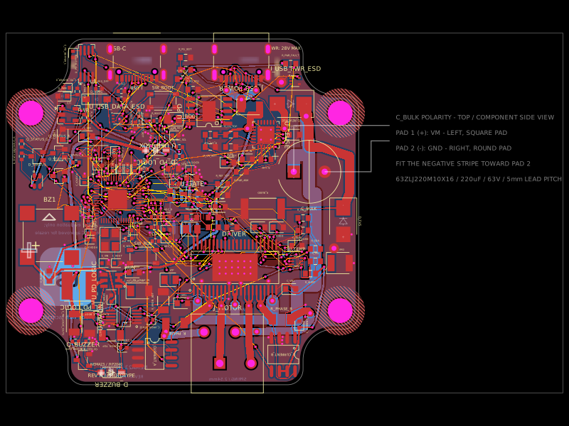 Similar packageimrishabh18/nema-23-stepper-controllerA 4-layer NEMA23 stepper-motor controller PCB combining an RP2040, DRV8462 dual-phase driver, USB-C Power Delivery/eFuse protection, current/voltage/temperature sensing, USB data multiplexing/ESD protection, optional AS5600 encoder, status LEDs, buzzer, and motor terminals.
 Discover something newabse/gameboy-advance