techmannih/nema34-mounted-stepper-controller
A USB-C PD-powered RP2040 motor controller with protected 48 V power, DRV8262 dual-bridge drive for a NEMA34 motor, regenerative-braking resistor, isolated sensing, hardware interlocks, and telemetry/status interfaces.
- Version
- 0.3.113
- License
- unset
- Stars
- 1
release/commissioning.md
PCB

Schematic

# NEMA34 programming and first motor test
This is the post-assembly operator workflow for the RP2040 / DRV8262DDV DATA-only revision. Software checks use fake peripherals; the measurements below are performed on the assembled board. The normal firmware archive is diagnostics-only. Two explicit test profiles are available without editing safety flags or changing the circuit.
| Image | Local START behaviour | Automatic limit |
|---|---|---|
| `diagnostics` | No motor-bus enable or motion | Inhibited |
| `power-test` | Enables protected VMOTOR with driver nSLEEP and both phase enables held low | Bus off and fault latched after 30 seconds; another press stops sooner |
| `bench-test` | Checks power, brake, nFAULT and current-reference command preparation, then runs unloaded motor | Request <=800 mA RMS (about 800 mA nominal after quantization), 10 rpm, 10 seconds then one-second stop ramp |
Every image starts disarmed. USB `ARM` never starts a motor. `DISARM`, fault, DATA loss and USB suspend stop immediately; they do not promise a controlled deceleration. The independent hardware brake and enable chain remain active. The 10-second limit is a commissioning limit, not a continuous-duty setting. Resetting/acknowledging a fault does not automatically restart.
Run the commands from the matching repository checkout with its dependencies installed. The release and firmware ZIPs mirror this procedure and blank record for the assembly team; they are not a standalone build environment.
## 1. Install and inspect with power removed
Use [thermal and mounting specification](thermal-qualification.md), [connector wiring](connector-harnesses.md), and the existing motor/brake assembly drawings. Start without an attached mechanical load. Secure the motor, board and brake assembly independently; do not suspend the board or heatsink from wires. Keep the shaft clear. The rear motor thread/depth still needs a physical determination before selecting motor case screws; the STEP provides axes, not thread engagement.
Check J1 POWER and J10 DATA identity, bulk-capacitor polarity, J2 coil pairs and J3 wiring. J3 pin 2 is BRAKE_RETURN, **not GND**. Check each coil pair with an ohmmeter, the approximately 10 ohm cold brake path, insulation and unpowered rail resistance. Do not attach or remove J2/J3 while energized. Put the physical PD disconnect within reach; USB DISARM cannot protect against a lost host.
## 2. Program and check the diagnostic images
Follow [PD programming](pd-programming.md) for the isolated U3 EEPROM fixture, TI fullFlash.bin at EEPROM address zero and 65,536-byte readback. Follow [firmware programming](../firmware/README.md) for the RP2040 UF2/SWD image and complete 4,194,304-byte readback at 0x10000000. Do not drive the board from the programmer's power output.
```sh
bun scripts/verify-programming.mjs --kind pd --serial BOARD_SERIAL --operator OPERATOR --programmer FIXTURE --readback /path/pd.bin --output /path/pd-check.json
bun scripts/verify-programming.mjs --kind rp2040 --serial BOARD_SERIAL --operator OPERATOR --programmer PROBE --readback /path/rp2040-diagnostics.bin --output /path/mcu-check.json
```
Keep the raw dumps and programmer logs. A copy of the input binary is not a device readback. Cold boot the MCU on DATA alone, then connect the actual EPR source/cable with the motor still disconnected. Verify RP2040 rails/reset/USB suspend behaviour and TPS APP boot/configuration identity. Capture `PROFILE`, `POWER`, `STATUS` and `DRIVER` over USB serial. DATA supplies the MCU; PD supplies the board/motor domain. PD_READY should require the live 48 V / 5 A contract plus fresh raw-PD ADC data. Protected VMOTOR is expected to be absent before local START in a test profile.
## 3. Build a stationary power-test image
Copy `engineering/commissioning-record.template.json` outside the repository. Fill the serial, exact PCB hash, operator, reviewer and timestamp. Each check contains `passed`, an evidence file path and its SHA-256 (for example `shasum -a 256 measurement.txt`). Paths are relative to the record. Supply both actual diagnostic-stage memory dumps under `readbacks`. Leave future checks false; `power-test` requires only the first five prerequisites. They are cold wiring/polarity, installed brake, secure guarded fixture, DATA rails/reset/suspend and PD APP cold boot. The tool checks hashes and image bytes; the named operator remains responsible for measurements and identity.
```sh
PIO=/path/to/pio bun scripts/build-firmware.mjs --profile power-test --record /path/board-record.json --out /path/new-power-test-build
```
This creates a separate ZIP with BIN/ELF/UF2, source hashes, limits, serial and record hash. It does not replace the diagnostics archive or assembly programming instructions. Flash it with PD removed, take a new full MCU readback, then check against that explicit archive:
```sh
bun scripts/verify-programming.mjs --kind rp2040 --archive /path/new-power-test-build/pd1180-power-test.zip --serial BOARD_SERIAL --operator OPERATOR --programmer PROBE --readback /path/power-test-readback.bin --output /path/power-test-check.json
```
Cold boot, inspect `PROFILE` and compare its record hash. With J2 disconnected and J3 installed, release then press START. Measure the eFuse ramp, PG, ADC scaling, enable-low state and driver rails. This profile does not enable the H-bridges, even if all readiness inputs are good. Capture source-loss, DATA-loss and stop behaviour without intentionally shorting power nets. The bus automatically switches off after 30 seconds. It may retain capacitor charge afterward: measure before handling. Investigate any reset/fault rather than repeatedly pressing START.
## 4. Build and run the bounded motor test
Power down. Connect the known unloaded motor with the documented coil pairs; fit the supported driver cooler/TIM, brake cooler/guard and strain relief. Add the stationary-power/fault records, installed-cooling inspection and motor-restraint evidence to a **new** record with `profile: "bench-test"`. These are prerequisites for the first motor test; this record does not require motor thermal/braking tests already to have passed.
```sh
PIO=/path/to/pio bun scripts/build-firmware.mjs --profile bench-test --record /path/bench-record.json --out /path/new-bench-test-build
```
Program and read back using `--archive /path/new-bench-test-build/pd1180-bench-test.zip` as above. Cold boot and compare PROFILE. Release/press START: live contract and temperature checks precede the bus ramp; current-reference command preparation and three distinct brake ADC pairs precede nSLEEP release, followed by 2 ms wake settling and phase enables. The startup deadline is 4 seconds, including the 1 uF ramp and sensor/driver settling. If it expires, outputs go low and the fault latches. Missing PG, stale ADC/I2C, driver nFAULT or open brake cannot be bypassed with START.
Observe the first 10-second run and automatic stop. Capture phase-current waveform, bus peak, case/PCB/resistor temperatures and faults. A second press requests a normal ramp-down; DISARM removes enable immediately. After a fault, one release/press acknowledges it and another is needed to start. The standard image has no reverse, arbitrary-current or arbitrary-speed command. Additional loading/thermal duty requires an explicitly reviewed operating profile and measurements; there is no hidden automatic promotion to 6 A.
## Software verification
`bun run check:firmware` exercises actual target call sites with fake PD/ADC/SPI/timer peripherals: delayed 1.45-second startup, DAC current-vector preparation, 200 ms readiness dwell, stationary nSLEEP/phase-enable inhibition, bounded phase sequencing, automatic stop, fault acknowledgement and suspend. Readback/profile tests reject altered images, short dumps, stale board identities and missing prerequisite evidence. These checks do not replace physical traces or measurements.
Measure U42 VOUTA/VOUTB and U7 IPROPI1/IPROPI2/current before accepting the first motor test. MCP4822 has no readback; neither a successful SPI transfer nor `DAC_COMMANDS_PREPARED` proves the analog output. Capture phase-current waveforms, zero crossings and fault shutdown.
Related Packages
 More from this authortechmannih/footprint-check-placementThis design features a 10mm x 10mm PCB with an integrated clock module chip connected to various digital, audio, and power nets, along with a nearby 100nF surface-mount capacitor for decoupling.
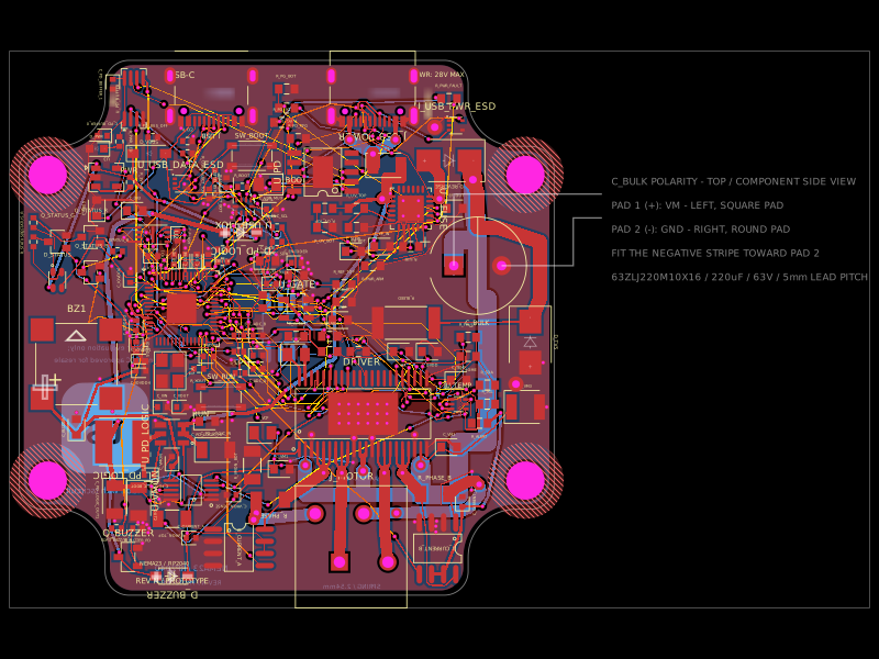 Similar packageimrishabh18/nema-23-stepper-controllerA 4-layer NEMA23 stepper-motor controller PCB combining an RP2040, DRV8462 dual-phase driver, USB-C Power Delivery/eFuse protection, current/voltage/temperature sensing, USB data multiplexing/ESD protection, optional AS5600 encoder, status LEDs, buzzer, and motor terminals.
 Discover something newabse/gameboy-advance