techmannih/nema34-mounted-stepper-controller
A USB-C PD-powered RP2040 motor controller with protected 48 V power, DRV8262 dual-bridge drive for a NEMA34 motor, regenerative-braking resistor, isolated sensing, hardware interlocks, and telemetry/status interfaces.
- Version
- 0.3.113
- License
- unset
- Stars
- 1
docs/system-overview.md
# NEMA34 system overview
Start with [the complete system](system-blocks/system-overview.svg), then open
[power domains](system-blocks/logic-power.svg),
[hardware protection](system-blocks/protection.svg), and
[control and telemetry](system-blocks/control-telemetry.svg).
Blue arrows are signals; dashed orange arrows are power. Two arrowheads indicate
two-way communication or returned motor energy, not two separate supplies.
The four pages answer four review questions, in order:
| Page | Review question |
| --- | --- |
| Motor Controller Architecture | Where do power and commands enter, and where do motor/brake energy go? |
| Power Distribution | Why are there three bucks, an LDO and supply-selection devices? What works with DATA alone or after PD loss? |
| Protection and Interlocks | What must be true before input power and motor drive are enabled? How does the independent brake respond? |
| Control and Telemetry | Which chip measures raw PD voltage, protected voltage, current and temperature? What does RP2040 control? |
Start with the seven functional blocks on page 1. Follow the PD input to the
protected motor supply and driver, then the separate controller and brake paths.
The power-stage group follows the PD-to-motor path, with the controller above
and the brake on a separate branch. The telemetry page puts RP2040 between
sensors and outputs, following the chart style of the reviewer's RVboy example. These are
explanatory boundaries, not galvanic-isolation or physical PCB boundaries.
Component references connect the overview to the detailed schematic. `PD_READY`
is firmware-derived; the physical eFuse `MOTOR_PG` is a different signal.

## How the board operates
1. J1 receives USB-C PD power. U1 protects CC and U2 negotiates the configured
48 V / 5 A EPR contract using U3's EEPROM image. U5 can power logic before
motor power is enabled. J10 provides USB data and the required MCU power. U39/U40 isolate the independently powered board I/O.
2. RP2040 checks the PD contract and configuration, raw input voltage from U38,
temperature, fresh telemetry and fault inputs before requesting motor power. PD_READY
is a firmware decision; it is not the same signal as the eFuse's MOTOR_PG.
3. U4 requires both PD_PATH_OK and POWER_PERMIT before enabling U6. The separate
U10/U11/U33 chain requires MCU_RUN, MOTOR_PG, VMOTOR_OK and TEMP_OK to enable
the motor driver. After motor power comes up, firmware additionally requires
valid protected-bus voltage, driver readiness and brake preflight before
asserting MCU_RUN. Reset defaults disable motion.
4. U7 regulates winding current using its integrated H-bridges. RP2040 supplies
PH/EN and MCP4822 current references configuration. J2's four WAGO poles connect to the two motor
windings. The motor's 6 A/phase label is not an approved operating setting.
5. Deceleration or an externally driven motor can return energy to VMOTOR.
U13 switches the independent Q16 brake near 52 V; J3's external resistor
dissipates the energy. U22 backs the control rail from VMOTOR and U34 provides
12 V brake-gate power during PD loss. The selected first-article resistor is 10 ohm / 300 W; install its specified
cooler/guard and record the load-dependent duty and temperatures.
DATA alone can boot RP2040 and its flash for diagnostics. The phase amplifiers and optional encoder use a switched DATA-derived rail; firmware keeps that rail off until board power-good permits peripheral startup. DATA cannot power the motor or the PD-side ADC/temperature sensors. PD alone cannot boot RP2040. U18 is an optional, unpopulated encoder, with no
qualified magnet mounting or closed-loop motion claim. See
[the IC-purpose table and power states](usb-pd-architecture.md) for details.
## View and regenerate
The default routed `release/circuit.json` contains the four native
`system_block_page` records plus their blocks, routes and actual PCB-component
associations. Use the **System** tab and page selector in a supporting viewer.
On tscircuit.com it appears immediately after **Files**, but only when the
selected release contains the diagrams. For an unmerged electrical revision, select its matching PR preview; main displays only merged artifacts.
Local preview: `bun run dev:system`. The SVG links above remain usable even if a
website deployment has not yet enabled its System tab.
`bun run build:pcb` rebuilds current source and the assembly, adds the diagrams,
checks the existing native-route fingerprint/DRC, and refreshes the default
viewer. Commit the refreshed generated files with source edits: a hosted rebuild
of an old committed `release/circuit.json` cannot update its schematic or diagram.
Run `bun run check:system` to reject missing/stale diagram metadata.
Authoring uses the official [system-block API](https://github.com/tscircuit/docs/pull/980)
in `system-overview.tsx`. The board stays on core 0.0.2112 and schematic-symbols
0.0.248; only the diagram layout uses the separately pinned core 0.0.2268 and
SVG renderer 0.0.455. The full-core upgrade experiment changed 908 solder-paste
records to 876 and changed schematic output, so it was not adopted for this
documentation change. CLI 0.0.3084 supports the newer viewer while the compatible
board compiler remains pinned.
The diagram generator seeds only existing source/PCB component identities into
the isolated renderer and appends only `system_block_*` records. It does not
generate replacement footprints or electrical connections. Tests reject missing
or ambiguous component links and prove all non-system records are preserved.
The pages use the native core's graph layout and `systemblock.group` boundaries.
Short node labels identify each function and its ICs; arrows carry power or
interface names. The overview follows the motor-power flow, the control page
centres on RP2040, and the independent brake stays separate from the enable
logic. Detailed operating conditions are described above and in the linked
architecture document instead of filling the diagram with text.
No fixed grid, manual coordinates or post-render geometry overrides are applied.
The same native layout is used in the live System tab and exported SVGs. All four
pages were visually reviewed for readable labels, grouping and unobstructed
connections.
Use [assembly](assembly.md) for parts allocation, fabrication/process review and
installation, then [commissioning](commissioning.md) for programming and the
diagnostic, stationary-power and bounded-motor sequence.
Related Packages
 More from this authortechmannih/footprint-check-placementThis design features a 10mm x 10mm PCB with an integrated clock module chip connected to various digital, audio, and power nets, along with a nearby 100nF surface-mount capacitor for decoupling.
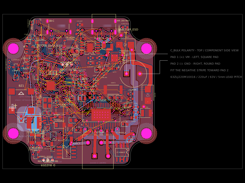 Similar packageimrishabh18/nema-23-stepper-controllerA 4-layer NEMA23 stepper-motor controller PCB combining an RP2040, DRV8462 dual-phase driver, USB-C Power Delivery/eFuse protection, current/voltage/temperature sensing, USB data multiplexing/ESD protection, optional AS5600 encoder, status LEDs, buzzer, and motor terminals.
 Discover something newabse/gameboy-advance