techmannih/nema34-mounted-stepper-controller
A USB-C PD-powered RP2040 motor controller with protected 48 V power, DRV8262 dual-bridge drive for a NEMA34 motor, regenerative-braking resistor, isolated sensing, hardware interlocks, and telemetry/status interfaces.
- Version
- 0.3.113
- License
- unset
- Stars
- 1
docs/first-article-checklist.md
# First-article checklist

**Status on 2026-11-07: no board has been built, programmed or powered.** None of the items below has a physical result yet. Passing CI does not show that the board works.

This page lists what still has to happen and where. The detailed procedures stay in [bring-up](bring-up.md), [commissioning](commissioning.md), [PD programming](pd-programming.md), [firmware](../firmware/README.md) and [thermal qualification](thermal-qualification.md). Follow them; if this page and a procedure disagree, stop and resolve the difference first.

## What can and cannot be done without a board

| Item | Checked without a board | Needs the assembled board |
|---|---|---|
| U3 EEPROM | `bun scripts/check-pd-image.mjs` passes: the TI image and its register regions match the reviewed settings | Writing U3, reading it back, cold boot, and the real 48 V contract |
| Crystal | Net connections, load calculation and the startup delay in the built firmware | Oscillator startup, frequency and USB enumeration |
| Motor | Firmware tests with fake peripherals, the 800 mA RMS firmware limit, and the current calculation | Phase current, temperature, stopping and fault behaviour |

## Decide before ordering

These can be closed now and are still open:

- [ ] **Website download.** Download the KiCad file from the tscircuit website and confirm MOTOR_A2 is connected. `website_roundtrip_verified` is still `false`; only an emulation has been run.
- [ ] **USB hole clearance.** Agree the 8 retained J1/J10 hole-clearance errors with the fabricator.
- [ ] **Fabrication review.** Confirm via filling and capping, stackup, final BOM/CPL, and the 0.45/0.30 mm encoder via with its 0.075 mm annular ring.
- [ ] **Stock.** Re-check stock on the order day.
- [ ] **EEPROM fixture.** Plan how U3 will be programmed. The pogo fixture has not been built.

## Work through these in order

Keep the motor disconnected until section 3. Record every result against the board serial number.

### 1. U3 EEPROM

**Why it needs the board:** U3 is a physical part and arrives blank. If the TPS26750 finds no valid configuration it waits for a host, so **the board will not negotiate 48 V until U3 is programmed**. USB DATA and MCU SWD cannot program a blank U3.

**Already checked:** the candidate is `fullFlash.bin` in `release/pd1180-ti-configuration.zip`, SHA-256 `ae4222fe41cde5bb9704b4b949fb67aaf231fc897d429199420a99db725b5d18`. `docs/pd-image-check.json` records `programmed: false` and `readback_verified: false`.

**Steps** (full detail in [PD programming](pd-programming.md)):

1. Connect the fixture to the bare top-side pads, with the motor and brake load disconnected and VMOTOR discharged.
2. Hold TP_PD_ISO low, and apply a current-limited **fixed 5 V to J1**. Do not negotiate EPR during programming.
3. Write the full image at 100 kHz with a 3.3 V open-drain programmer, at 7-bit address 0x50.
4. Read back all 65,536 bytes and compare them:

   ```sh
   bun scripts/verify-programming.mjs --kind pd --serial BOARD_SERIAL --operator OPERATOR --programmer FIXTURE --readback /path/pd.bin --output /path/pd-check.json
   ```

5. Remove power, release TP_PD_ISO, and cold boot on fixed 5 V.
6. Connect the real 48 V / 5 A EPR source and cable, with the motor still disconnected.

**Pass:** the readback comparison passes, the TPS26750 enters APP mode with the intended configuration, and raw PD_VBUS reads a real 48 V contract. A matching readback alone does not prove a cold boot or a contract.

**If it fails:** stop. Do not continue to motor tests, and do not retry with EPR connected to the programming setup.

### 2. Crystal and USB

**Why it needs the board:** whether a crystal starts reliably depends on the real part, the copper and the assembly. It cannot be calculated.

**Already checked:**

| Point | Result |
|---|---|
| C50 connection | Moved to `XTAL_OUT` in PR #29. This fix has not been tested on hardware |
| Crystal part | Y1 is ABM8-272-T3, the crystal Raspberry Pi recommends. Pinout and land fit were checked against the [Abracon datasheet](https://abracon.com/datasheets/ABM8-272-T3.pdf), and no copper changed; see `sourcing/crystal-substitution.json` |
| Load | 15 pF / 2 + an assumed 3 pF stray = 10.5 pF, against 10 pF. The stray value is Raspberry Pi's assumption, not a measurement of this layout |
| Firmware startup delay | The built image writes 3008 to `XOSC.STARTUP` (47 × 64). This only applies once our firmware runs, not to the ROM USB bootloader |

The recommended part does not prove this board: oscillator startup still depends on the real layout and assembly. C49 and C50 sit farther from Y1 than on the Raspberry Pi reference, and C50 reaches Y1 through a longer trace, so stray capacitance may be higher than assumed.

**Steps:**

1. With the board unpowered, confirm C50 sits between `XTAL_OUT` and GND, and R138 between `OSC_OUT` and `XTAL_OUT`.
2. Power from J10 DATA only. Measure V3V3_MCU and V1V1_MCU.
3. Enter ROM USB boot through TP_BOOTSEL and check that the board enumerates. If it does not, try [SWD](../firmware/README.md) and record both results. A clock fault and a USB fault look alike here.
4. Program the diagnostic image and read back all 4,194,304 bytes:

   ```sh
   bun scripts/verify-programming.mjs --kind rp2040 --serial BOARD_SERIAL --operator OPERATOR --programmer PROBE --readback /path/rp2040-diagnostics.bin --output /path/mcu-check.json
   ```

5. Cold boot repeatedly on DATA, with power fully removed each time. Repeat with the board cold and after it has warmed up, and across more than one board if available.
6. Measure the frequency with a low-capacitance active probe at the C50 pad. An ordinary probe adds enough capacitance to shift the frequency or stop the oscillator.

**Suggested pass, until the project sets a stricter limit:** 20 of 20 cold boots enumerate at each temperature, and the frequency is within Y1's tolerance. Y1 is listed at ±30 ppm tolerance and ±30 ppm stability, and USB full speed allows ±2,500 ppm. These counts are a starting point, not a qualification.

**If it fails:** check Y1, C49, C50 and R138 assembly first. Then measure the stray capacitance and review the C49 and C50 value. Do not continue to the power tests until this is stable.

### 3. Motor and current

**Why it needs the board:** the software checks use fake peripherals. Real current, heat and regeneration can only be measured.

**Already checked:** the firmware rejects any request above `DRV8262_BENCH_RMS_MA` (800 mA RMS). The default image never enables the motor. At 800 mA RMS the calculated peak is 1.131 A, which needs about 0.36 V on `VREF` with the 1.5 kΩ IPROPI resistors.

**Stages, in this order** (full detail in [commissioning](commissioning.md)):

| Stage | Image | Motor (J2) | Cooling | Limit |
|---|---|---|---|---|
| Diagnostics | `diagnostics` | Disconnected | Not needed | Motor bus and motion inhibited |
| Stationary power | `power-test` | Disconnected, J3 fitted | Per [commissioning](commissioning.md) | Bus off after 30 s; H-bridges stay disabled |
| First motion | `bench-test` | Unloaded motor, restrained | **Driver cooler and TIM, brake cooler and guard fitted** | 800 mA RMS or less, 10 rpm, 10 s |

Each test image is built from a completed record of the earlier stage, then programmed and read back. Check every coil pair with an ohmmeter, and remember that J3 pin 2 is BRAKE_RETURN, **not GND**.

**Measure during first motion:** U42 VOUTA and VOUTB, U7 IPROPI1 and IPROPI2, the phase-current waveform, bus peak, case, PCB and resistor temperatures, stopping, and fault behaviour. MCP4822 has no readback, so a successful SPI command does not prove the analog output.

**Pass:** the measured values match the request and the run stops by itself at 10 s. Stop on any fault or unexpected reading.

**More than 800 mA RMS is not available today.** It needs all of the following:

- [ ] Measured results from the stages above.
- [ ] A selected and fitted heatsink. ATS-TI1OP-519-C1-R3 is a reference candidate only, and its fit has not been checked.
- [ ] A chosen current, waveform and duty for the motor. The motor's 6 A rating is not an approved setpoint.
- [ ] A regeneration decision. The 100 µs delayed-recovery case reaches 54.745 V and fails the 0.5 V reserve, and the 5 J / 20 ms stress exceeds 55 V. See [thermal qualification](thermal-qualification.md).
- [ ] A new firmware profile and its review. The current image cannot exceed 800 mA RMS.

## Done means

The first article is finished only when sections 1 to 3 have recorded results for a named board serial and image hash. Until then, describe this board as **unqualified hardware**.
Related Packages
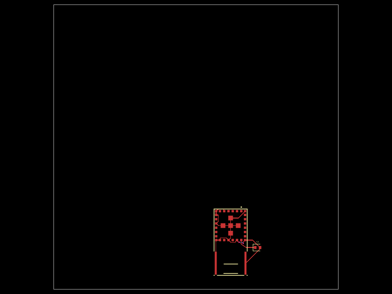 More from this authortechmannih/footprint-check-placementThis design features a 10mm x 10mm PCB with an integrated clock module chip connected to various digital, audio, and power nets, along with a nearby 100nF surface-mount capacitor for decoupling.
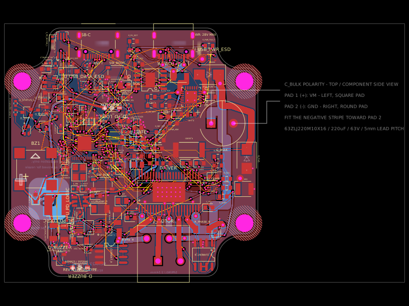 Similar packageimrishabh18/nema-23-stepper-controllerA 4-layer NEMA23 stepper-motor controller PCB combining an RP2040, DRV8462 dual-phase driver, USB-C Power Delivery/eFuse protection, current/voltage/temperature sensing, USB data multiplexing/ESD protection, optional AS5600 encoder, status LEDs, buzzer, and motor terminals.
 Discover something newabse/gameboy-advance