shibosoftwaredev/f1c100s-linux-nema8-stepper-controller
Restores component part numbers and CAD models, removes test-point 3D bodies, and validates that solder paste exists only on top-side SMT pads without altering copper or DRC.
- Version
- 0.3.5
- License
- unset
- Stars
- 0
work/publish/README.md
# F1C100S Linux motor controller

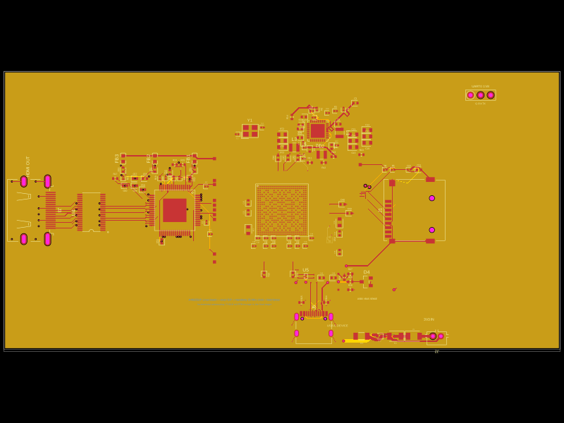
An 84 × 52 mm, four-layer tscircuit board combining the proven F1C100S Linux
carrier with a protected DRV8825 bipolar stepper-motor stage. The design keeps
the original USB FEL, SPI flash, UART, SPI1 and I²C0 interfaces, and uses Linux
GPIO for STEP/DIR control. A TMP102 monitors temperature near the motor driver.

This design is fabrication-ready in the sense that its generated circuit has
zero emitted DRC errors, `tsci check` reports zero errors, Gerber-mode
`tsci check shorts` reports no shorts, and the fabrication exports match the
verified circuit. The modified hardware has not yet been physically assembled
or validated; first articles still require careful bring-up and measurement.

## Motor stage

- DRV8825PWPR, fixed at 1/16 microstepping.
- 9–20 V motor input through a 2 A resettable fuse and reverse-polarity diode.
- 22 V bidirectional TVS, 22 µF/50 V bulk capacitor and 10 µF/50 V ceramic input capacitor.
- 6.8 kΩ / 2.0 kΩ VREF divider and 0.30 Ω sense resistors set about 0.5 A peak per phase.
- Hardware-safe startup: 100 kΩ pulldown keeps nSLEEP and nRESET low until Linux drives PE4 high.
- nENBL is tied active, while PE4 controls both nSLEEP and nRESET; disabling PE4 removes bridge drive.
- Twelve 0.30/0.45 mm thermal vias under and around the PowerPAD.
- Phase routing uses short 0.12 mm pin necks and 0.30 mm long trunks; the protected motor-input path is 0.80 mm.

The motor supply does **not** power the Linux rails. Power the logic side from
USB-C 5 V and connect a shared-ground 9–20 V supply to `J_VM`. Confirm polarity
before applying motor power. The 0.5 A setting is intentionally conservative;
do not change current-regulation values without a thermal and electrical review.

## Linux GPIO and connectors

| F1C100S pin | Function | Direction / polarity |
|---|---|---|
| PE2 | DRV8825 STEP | Output, rising-edge step |
| PE3 | DRV8825 DIR | Output |
| PE4 | Motor enable | Output, high wakes nSLEEP/nRESET |
| PE5 | DRV8825 nFAULT | Input, active low, 10 kΩ pull-up |
| PE6 | TMP102 ALERT | Input, active low, 10 kΩ pull-up |

`J_MOTOR` is JST-PH, 2.00 mm pitch: pin 1 A+, pin 2 A−, pin 3 B+,
pin 4 B−. Verify the two coil pairs with an ohmmeter before connection.

`J_VM` is the 5.08 mm motor-power terminal: pin 1 positive, pin 2 ground.
Use 9–20 V only. Do not connect motor power to USB VBUS or a 3.3 V pin.

The original `J_SPI` and `J_I2C` JST-PH headers remain available:

| Pin | J_SPI | J_I2C |
|---|---|---|
| 1 | Ground | Ground |
| 2 | +3.3 V output | +3.3 V output |
| 3 | SPI1 clock / PE9 | I²C0 SDA / PE12 |
| 4 | SPI1 MOSI / PE8 | I²C0 SCL / PE11 |
| 5 | SPI1 MISO / PE10 | — |
| 6 | SPI1 CS / PE7 | — |

TMP102 is at I²C address `0x48`. UART pads are TX, RX and GND at 3.3 V logic.
USB-C is a USB 2.0 device/sink port for 5 V and FEL, not a host or USB-PD port.

## Build and verification

Use the pinned dependencies and deterministic stored route set:

```sh
npm ci
node work/build-fixed-board-traces.mjs
npm run typecheck
npm run build
npm run verify
npm run check
npm run check:shorts
npm run export:fabrication
```

`verification.json` checks the board dimensions and layer count, all emitted DRC
errors, exact 0.30 mm drill / 0.45 mm pad dimensions for every via, component
bounds, single-sided assembly, motor connectivity and safe defaults, thermal
vias, JLCPCB IDs, and the stock-audit hash. `reports/jlcpcb-stock-audit.json`
contains the dated JLCPCB availability result. Inventory is not reserved and
must be reconfirmed when the order is placed.

The editable top level is `index.circuit.tsx`; the motor stage is in
`motor-stage.tsx`. `saved-board-traces.json` is the deterministic board route
set. Generated previews and circuit JSON are under `dist/index/`, while the
orderable package is under `fabrication/`.

## Linux integration

Merge `firmware/carrier.dtsi` into the complete board device tree. It enables
SPI flash, UART0, I²C0 with TMP102, SPI1 and USB peripheral mode. The file is a
fragment, not a complete bootable device tree or Linux image.

Install Python 3 and libgpiod 2.x bindings, confirm the GPIO chip and line names
with `gpioinfo`, then start with an uncoupled motor at low speed:

```sh
python3 firmware/motor-control.py --dry-run --steps 3200 --hz 100
python3 firmware/motor-control.py --chip /dev/gpiochip0 --steps 3200 --hz 100
```

The utility disables the driver before configuration and on every exit, checks
nFAULT and TMP102 ALERT while moving, and can enforce an hwmon temperature
limit. Linux userspace GPIO is not real-time and has pulse jitter; use a kernel
PWM/timer solution or a motion coprocessor for precise or high-rate motion.

## Boot and first-article safety

Fit `JP_BOOT` for normal SPI-flash boot. Remove it during power-up to enter USB
FEL recovery. The SPI flash is blank unless programmed with a suitable
F1C100S SPL/U-Boot/Linux image configured for this pinout and 32 MiB RAM.

For first power-up, leave `J_VM` disconnected and verify the 3.3 V, 2.8 V,
2.5 V and 1.2 V rails. Then connect a current-limited motor supply without a
motor, confirm PE4 holds the bridge asleep, and inspect VREF, nFAULT and TMP102.
Finally test at low step rate with the motor mechanically unloaded. Monitor the
DRV8825, regulators, sense resistors and motor temperature.

## Fabrication notes

- Four copper layers are required; there is no guaranteed uninterrupted plane.
- All fitted components are on the top side; only a top paste stencil is needed.
- All 241 vias are exactly 0.30 mm finished drill and 0.45 mm pad diameter.
- The motor-current and high-current traces should be reviewed against the chosen copper weight and process.
- USB differential impedance depends on the fabricator's actual stackup and still needs signal-integrity review.
- Stock checks establish public availability, not sourcing reservation, assembly eligibility at checkout, or electrical validation.

The board was derived from the tested
[F1C100S Linux dev board](https://tscircuit.com/seveibar/f1c100s-linux-dev-board)
and follows the architecture of the referenced
[RP2040 motor controller](https://tscircuit.com/imrishabh18/rp2040-motor-controller#files).
Design annotations and review artifacts follow the requested tscircuit handbook
revision `0c951d65be1b0bbddf989f8179e8591b0441ec8f`.
Related Packages
 More from this authorShiboSoftwareDev/am625sip-linux-boardThis code defines the physical footprint and pin layout for an AM625 System-in-Package (SIP) component, detailing pad positions, pin labels, and package outline for hardware integration.
 Similar packageaura/diy-power-delivery-triggerThis hardware design implements a USB Type-C port with supporting power management and signal conditioning components, including a USB-C connector, a FUSB302 USB-C port controller, ESD protection diodes, a buck converter for 3.3V power regulation, an STM32 microcontroller for control and processing, an RGB LED indicator, push button, terminal block connections, and associated filtering and support components.
 Discover something newtscircuit/standard-jst-programmer26 × 42 mm USB-C RP2040 programmer with JST and TC2030 IDC SWD, NRST, selectable sensed 5 V / 3.3 V power, RGB status, and importable JST SH/Tag-Connect targets. Top-side assembly.