shibosoftwaredev/f1c100s-linux-nema8-stepper-controller
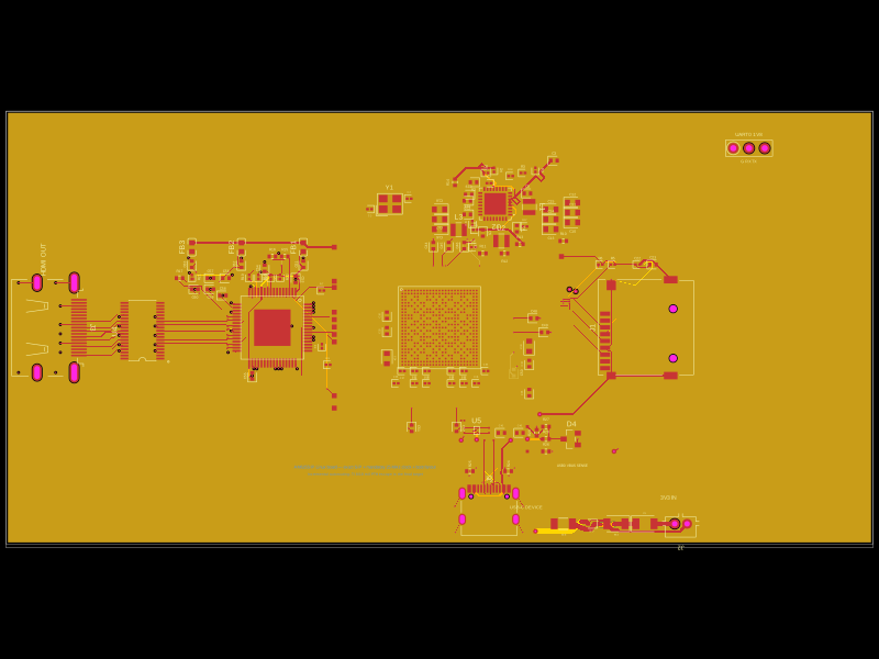
Restores component part numbers and CAD models, removes test-point 3D bodies, and validates that solder paste exists only on top-side SMT pads without altering copper or DRC.
- Version
- 0.3.5
- License
- unset
- Stars
- 0
motion-controller.tsx
import { STM32G030F6P6 } from "./imports/STM32G030F6P6"
import { BSS84_7_F } from "./imports/BSS84_7_F"

const wire = (name: string, from: string, to: string, thickness = 0.15) =>
  <trace name={name} from={from} to={to} thickness={thickness} />

const resistor = (name: string, value: string, lcsc: string, x: number, y: number) =>
  <resistor name={name} resistance={value} footprint="0402"
    supplierPartNumbers={{jlcpcb:[lcsc]}} pcbX={x} pcbY={y} schX={x} schY={y} />

const smdTestPoint = <footprint>
  <smtpad portHints={["pin1"]} pcbX={0} pcbY={0} width="1.5mm" height="1.5mm" shape="rect" />
</footprint>

/**
 * The STM32G0 owns STEP/DIR, driver enable and temperature polling. Linux sends
 * framed UART commands and a heartbeat, but never generates step pulses. The
 * MCU firmware must enable its independent watchdog and enforce a command
 * timeout. Reset/BOOT0 are driven by Linux so field firmware updates can use the
 * STM32 ROM UART bootloader. Both reset and loss of PD force the bridge asleep.
 */
export function MotionController() {
  return <group name="MOTION" pcbX={0} pcbY={0} schX={-30} schY={25.5} schSheetName="motion">
    <STM32G030F6P6 name="U_MOTION" pcbX={18} pcbY={-21} pcbRotation={0}
      schX={18} schY={-22}
      noConnect={["PB7_PB8","PB9_PC14_OSC32_IN","PC15_OSC32_OUT","PA1","PB0_PB1_PB2_PA8","PB3_PB4_PB5_PB6"]} />
    <capacitor name="C_MOTION" capacitance="100nF" maxVoltageRating={16} footprint="0402"
      maxDecouplingTraceLength={10}
      supplierPartNumbers={{jlcpcb:["C1525"]}} pcbX={17.35} pcbY={-26} schX={12} schY={-20} />
    <capacitor name="C_MOTION_BULK" capacitance="4.7uF" maxVoltageRating={25} footprint="0805"
      manufacturerPartNumber="CL21A475KAQNNNE" supplierPartNumbers={{jlcpcb:["C1779"]}}
      pcbX={11} pcbY={-25} schX={12} schY={-23} />
    {wire("MOTION_VDD", ".U_MOTION > .pin4", "net.V3V3", 0.3)}
    {wire("MOTION_GND", ".U_MOTION > .pin5", "net.BOARD_GND", 0.3)}
    <trace name="MOTION_BYPASS_VDD" from=".C_MOTION > .pin1" to=".U_MOTION > .pin4"
      thickness={0.12} pcbStraightLine />
    <trace name="MOTION_BYPASS_GND" from=".C_MOTION > .pin2" to=".U_MOTION > .pin5"
      thickness={0.12} maxLength={3} pcbStraightLine />
    {wire("MOTION_BULK_VDD", ".C_MOTION_BULK > .pin1", "net.V3V3", 0.3)}
    {wire("MOTION_BULK_GND", ".C_MOTION_BULK > .pin2", "net.BOARD_GND", 0.3)}

    {/* Linux-to-MCU UART and the two programming controls. */}
    {wire("MOTION_UART_TX", ".U_MOTION > .pin9", "net.MOTION_TX")}
    {wire("MOTION_UART_RX", ".U_MOTION > .pin10", "net.MOTION_RX")}
    {wire("MOTION_NRST", ".U_MOTION > .NRST", "net.MOTION_NRST")}
    {wire("MOTION_BOOT", ".U_MOTION > .pin19", "net.MOTION_BOOT")}
    {resistor("R_MOTION_RESET", "10k", "C25744", 24, -19)}
    <resistor name="R_MOTION_BOOT" resistance="100k" footprint="0402"
      supplierPartNumbers={{jlcpcb:["C25741"]}} pcbX={15.72} pcbY={-15.5} pcbRotation={90}
      schX={24} schY={-22} />
    <capacitor name="C_MOTION_RESET" capacitance="100nF" maxVoltageRating={16} footprint="0402"
      supplierPartNumbers={{jlcpcb:["C1525"]}} pcbX={24} pcbY={-25} schX={24} schY={-25} />
    {wire("MOTION_RESET_PULLUP", ".R_MOTION_RESET > .pin1", "net.MOTION_NRST")}
    {wire("MOTION_RESET_PULLUP_VDD", ".R_MOTION_RESET > .pin2", "net.V3V3")}
    {wire("MOTION_RESET_CAP", ".C_MOTION_RESET > .pin1", "net.MOTION_NRST")}
    {wire("MOTION_RESET_CAP_GND", ".C_MOTION_RESET > .pin2", "net.BOARD_GND")}
    <trace name="MOTION_BOOT_PULLDOWN" from=".U_MOTION > .pin19" to=".R_MOTION_BOOT > .pin1"
      thickness={0.15} pcbStraightLine />
    {wire("MOTION_BOOT_PULLDOWN_GND", ".R_MOTION_BOOT > .pin2", "net.BOARD_GND")}

    {/* Timer output and safety inputs own the motor stage. */}
    {wire("MOTION_STEP", ".U_MOTION > .pin13", "net.MOTOR_STEP")}
    {wire("MOTION_DIR", ".U_MOTION > .pin14", "net.MOTOR_DIR")}
    {wire("MOTION_ENABLE_RAW", ".U_MOTION > .pin11", "net.MOTOR_ENABLE_RAW")}
    {wire("MOTION_FAULT", ".U_MOTION > .pin12", "net.MOTOR_FAULT")}
    {wire("MOTION_TEMP_ALERT", ".U_MOTION > .pin7", "net.MOTION_TEMP_ALERT")}
    {wire("MOTION_I2C_SCL", ".U_MOTION > .pin16", "net.MOTION_I2C_SCL")}
    {wire("MOTION_I2C_SDA", ".U_MOTION > .pin17", "net.MOTION_I2C_SDA")}

    {/* PG-low turns on the P-channel pass gate. Any reset leaves both sides low. */}
    <BSS84_7_F name="Q_PD_ENABLE" pcbX={28} pcbY={-17} pcbRotation={90}
      schX={29} schY={-18} />
    {resistor("R_MOTION_ENABLE_PD", "100k", "C25741", 28, -21)}
    {resistor("R_MOTOR_ENABLE_PD", "100k", "C25741", 31, -17)}
    {wire("PD_GATE_SOURCE", ".Q_PD_ENABLE > .S", "net.MOTOR_ENABLE_RAW")}
    {wire("PD_GATE_DRAIN", ".Q_PD_ENABLE > .D", "net.MOTOR_ENABLE")}
    {wire("MOTION_ENABLE_RAW_PD", ".R_MOTION_ENABLE_PD > .pin1", "net.MOTOR_ENABLE_RAW")}
    {wire("MOTION_ENABLE_RAW_PD_GND", ".R_MOTION_ENABLE_PD > .pin2", "net.BOARD_GND")}
    {wire("MOTOR_ENABLE_PD", ".R_MOTOR_ENABLE_PD > .pin1", "net.MOTOR_ENABLE")}
    {wire("MOTOR_ENABLE_PD_GND", ".R_MOTOR_ENABLE_PD > .pin2", "net.BOARD_GND")}

    {/* Factory/recovery access only; these are compact SMD pads, not expansion headers. */}
    {[
      ["SWDIO", ".U_MOTION > .pin18", 11],
      ["SWCLK", ".U_MOTION > .pin19", 14],
      ["NRST", "net.MOTION_NRST", 17],
      ["GND", "net.BOARD_GND", 20],
    ].map(([label, target, x]) => <group key={label as string} pcbX={0} pcbY={0} schX={0} schY={0}>
      <testpoint name={`TP_MOTION_${label}`} footprint={smdTestPoint}
        pcbX={x as number} pcbY={-34} schX={x as number} schY={-34} />
      {wire(`MOTION_TP_${label}`, `.TP_MOTION_${label} > .pin1`, target as string)}
      <silkscreentext text={label as string} pcbX={x as number} pcbY={-35.5} fontSize={0.55} />
    </group>)}

    <silkscreentext text="STM32 MOTION / WATCHDOG" pcbX={19} pcbY={-28} fontSize={0.65} />
  </group>
}
Related Packages
 More from this authorShiboSoftwareDev/am625sip-linux-boardThis code defines the physical footprint and pin layout for an AM625 System-in-Package (SIP) component, detailing pad positions, pin labels, and package outline for hardware integration.
 Similar packageaura/diy-power-delivery-triggerThis hardware design implements a USB Type-C port with supporting power management and signal conditioning components, including a USB-C connector, a FUSB302 USB-C port controller, ESD protection diodes, a buck converter for 3.3V power regulation, an STM32 microcontroller for control and processing, an RGB LED indicator, push button, terminal block connections, and associated filtering and support components.
 Discover something newtscircuit/standard-jst-programmer26 × 42 mm USB-C RP2040 programmer with JST and TC2030 IDC SWD, NRST, selectable sensed 5 V / 3.3 V power, RGB status, and importable JST SH/Tag-Connect targets. Top-side assembly.