shibosoftwaredev/f1c100s-linux-nema8-stepper-controller
Restores component part numbers and CAD models, removes test-point 3D bodies, and validates that solder paste exists only on top-side SMT pads without altering copper or DRC.
- Version
- 0.3.5
- License
- unset
- Stars
- 0
README.md
# F1C100S Linux NEMA 8 stepper controller

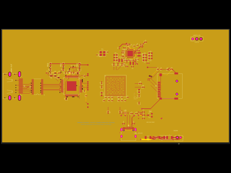
An 81 × 70 mm, four-layer tscircuit board for the **StepperOnline
8HS15-0604S**: a 20 × 20 × 38 mm, four-wire bipolar NEMA 8 stepper rated
0.6 A/phase. The motor connects by cable to the JST-PH output; this PCB is not
intended to mount mechanically on the motor.

The board combines the tested F1C100S Linux carrier with:

- a DRV8825 set to approximately 0.58 A peak/phase and fixed 1/16 microstepping;
- an STM32G030 real-time motion/safety controller;
- a dedicated USB-C power receptacle with a HUSB238A PD sink requesting 15 V / 3 A;
- a TPS54302 5 V buck and the carrier's 3.3 V, 2.8 V, 2.5 V and 1.2 V rails;
- a W5500 and HR911105A jack for 10/100 Ethernet; and
- a second, dedicated USB-C receptacle for USB 2.0 FEL/gadget data.

Revision D moves the right-side mounting column and motor protection parts
inward, reducing the board width by 5 mm and its area by approximately 5.8%
without moving the DRV8825 or lengthening the motor phase paths.

There are no SPI or I²C expansion headers. SPI1 is dedicated to Ethernet, and
the STM32 owns the local temperature sensor. Compact SWD pads are provided for
factory and recovery use.

## Motor and connector

`J_MOTOR` is JST-PH, 2.00 mm pitch:

| Pin | Phase | 8HS15-0604S lead |
|---:|---|---|
| 1 | A+ | Black |
| 2 | A− | Green |
| 3 | B+ | Red |
| 4 | B− | Blue |

Confirm the two coil pairs with an ohmmeter before connection; wire colours can
change between motor revisions. The 15 V input is appropriate because the
DRV8825 regulates winding current. It must not be applied directly to a motor
winding.

The motor rail includes a 2 A resettable fuse, reverse-blocking diode, 22 V
bidirectional TVS and local bulk/ceramic capacitance. Twelve 0.30 mm drill /
0.45 mm pad thermal vias serve the DRV8825 PowerPAD. The phase traces request
0.30 mm copper and the protected input path requests 0.80 mm copper.

## Control and safety architecture

Linux never generates step pulses. It sends framed commands over UART0 to the
STM32G030; the STM32 timer generates STEP, controls DIR and enable, polls the
TMP102, and monitors DRV8825 nFAULT. The intended STM32 firmware must:

- enable the independent watchdog;
- keep the bridge disabled after reset;
- require a valid arm command before motion;
- require a heartbeat at least every 100 ms;
- disable the bridge if no valid command arrives for 250 ms; and
- latch off on driver fault or over-temperature.

The HUSB238A contract-valid output also gates the motor-enable path in hardware,
so loss of the requested PD contract forces the bridge asleep independently of
Linux and MCU software. F1C100S PE2/PE3 control STM32 BOOT0/reset for ROM-UART
updates. SWD remains available on bottom-edge test pads.

The proposed host/MCU wire protocol is documented in
[`firmware/PROTOCOL.md`](firmware/PROTOCOL.md). The Linux reference client is
[`firmware/motor-control.py`](firmware/motor-control.py). A matching STM32
firmware image is required before the hardware can move a motor.

## USB-C power, USB-C data and Ethernet

Use a USB-C PD source that offers a 15 V PDO with adequate current. The
HUSB238A is strapped for a 15 V / 3 A request with 11 kΩ VSET and 21 kΩ ISET.
Its raw VBUS input cold-starts the controller and is isolated from the system
rail by an HUSB238A-controlled AO4407A high-side switch. The USB receptacle and
power path are 20 V / 5 A-rated, but this board's design point is 15 V. A
non-PD 5 V source can power the logic buck, but the hardware interlock must keep
motor drive disabled without the valid requested contract.

`J_USB_PWR` is power-only and `J_USB_DATA` is the F1C100S USB2 device/FEL
connection. The DATA port has independent 5.1 kΩ CC pull-downs, while its VBUS
pads are intentionally unconnected. Keep the PD port attached while using FEL
or Linux USB gadget mode. This self-powered arrangement prevents a computer's
5 V rail and the PD-derived system rail from backfeeding each other.

The W5500 is a dedicated SPI1 peripheral with PE7 CS, PE8 MOSI, PE9 SCLK,
PE10 MISO, PE5 reset and PE6 interrupt. The Linux device-tree fragment in
[`firmware/carrier.dtsi`](firmware/carrier.dtsi) binds it as the system Ethernet
interface. UART0 is reserved for the motion MCU and must not be the Linux console.

## Build and verification

```sh
npm ci
npm run typecheck
npm run build
npm run render:schematics
npm run stock:audit
npm run verify
npm run check
npm run check:shorts
npx tsci check source index.circuit.tsx
npx tsci check pin_specification index.circuit.tsx
npm run export:fabrication
```

`scripts/verify.mjs` asserts the board outline/layers, zero emitted DRC errors,
exact 0.30/0.45 mm geometry for every routed via, component bounds, top-only
assembly, raw/switched USB-PD topology, W5500 MDI termination, motor and safety
connectivity, motor/power copper widths, JLCPCB IDs, and a stock-report hash
tied to the exact circuit JSON. Inventory is a point-in-time
snapshot, not a reservation; rerun the audit before ordering and review JLCPCB's
placement/polarity preview.

The schematic is split into seven functional sheets: SoC support, Linux
interfaces, unused SoC interfaces, USB-C PD/5 V power, SoC power rails,
Ethernet, and real-time stepper control. `npm run render:schematics` writes a
PNG and SVG for every sheet under `reports/schematic-sheets/` for visual review.

Generated circuit and previews are under `dist/index/`. The final Gerbers, BOM
and pick-and-place files are under `fabrication/` after export.

## First-article bring-up

This revision is fabrication-output checked, not yet physically validated.
Program the STM32 and Linux flash before attaching a motor. On a current-limited
PD bench setup, first verify 5 V, 3.3 V, 2.8 V, 2.5 V and 1.2 V; then verify the
15 V contract, motor-enable interlock, VREF, nFAULT, watchdog timeout and
temperature shutdown without a motor. Finally test an uncoupled motor at low
speed and monitor the driver, sense resistors, regulators and motor temperature.

The design derives from the tested
[F1C100S Linux development board](https://tscircuit.com/seveibar/f1c100s-linux-dev-board)
and takes USB-PD architecture inspiration from Rishabh's
[RP2040 reference design](https://tscircuit.com/imrishabh18/rp2040-motor-controller#files).
Review annotations follow tscircuit handbook commit
`0c951d65be1b0bbddf989f8179e8591b0441ec8f`.
Related Packages
 More from this authorShiboSoftwareDev/am625sip-linux-boardThis code defines the physical footprint and pin layout for an AM625 System-in-Package (SIP) component, detailing pad positions, pin labels, and package outline for hardware integration.
 Similar packageaura/diy-power-delivery-triggerThis hardware design implements a USB Type-C port with supporting power management and signal conditioning components, including a USB-C connector, a FUSB302 USB-C port controller, ESD protection diodes, a buck converter for 3.3V power regulation, an STM32 microcontroller for control and processing, an RGB LED indicator, push button, terminal block connections, and associated filtering and support components.
 Discover something newtscircuit/standard-jst-programmer26 × 42 mm USB-C RP2040 programmer with JST and TC2030 IDC SWD, NRST, selectable sensed 5 V / 3.3 V power, RGB status, and importable JST SH/Tag-Connect targets. Top-side assembly.