seveibar/pedometer
This hardware setup integrates a Type-C connector, battery, display, and RF antenna connected through a microcontroller, USB interface, charging and fuel gauge ICs, along with associated passive components, enabling power management, data communication, and signal processing.
- Version
- 0.4.4
- License
- unset
- Stars
- 1
CRYSTAL_ROUTING.md
# Zero-via crystal routing

Both 48 MHz crystal signals route entirely on top: X48P is 3.137 mm and X48N is 3.268 mm, with zero vias each. Y1 is at (9, 0) mm, rotated 315°. X48P has a source-defined bend at (8, 1.1) mm to clear the crystal ground pad; X48N is straight. Both use `maxViaCount={0}`.

The surrounding ground returns are routed explicitly on inner1: the crystal GND2 return joins the MCU exposed pad, and the first RF shunt returns to MCU ground. The C12 ground via is outside its pad to clear the charger signal. A small source-defined bend in the MCU-to-C21 RF trace resolves the final RF/supply crossing. All copper is defined in the TSX source; generated JSON is unmodified.

The accepted cold-cache build uses stock beta_pipeline9 at 100× effort, without phases, breakout directives or custom algorithms. Full-board raw DRC and continuity checks report zero errors; logical design and TypeScript checks pass. The complete board has 52 components, 138 PCB traces and 122 vias. The zero-via result applies to the crystal signals, not their ground returns or the whole board.

## Iterations

Trials are preserved under `work/crystal-zero/` in the workspace. Placement and crystal routing were established first, followed by one local routing adjustment at a time. Trial 08 completed the board with one RF/supply crossing. Trial 13 changes only the RF path from trial 08 and completes full-board routing with zero raw errors.

This supersedes the v0.4.2 two-via crystal result. Hardware oscillator and RF validation remain outstanding.
Related Packages
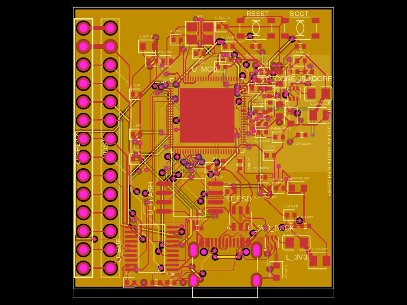 More from this authorseveibar/spi-display-webcam-interceptorThis collection of code defines various hardware components, including an crystal oscillator, microcontroller, voltage regulators, inductors, connectors, and logic gates, each represented with physical footprint, pin configurations, and 3D CAD models for PCB design and integration.
 Similar packageaura/diy-power-delivery-triggerThis hardware design implements a USB Type-C port with supporting power management and signal conditioning components, including a USB-C connector, a FUSB302 USB-C port controller, ESD protection diodes, a buck converter for 3.3V power regulation, an STM32 microcontroller for control and processing, an RGB LED indicator, push button, terminal block connections, and associated filtering and support components.
 Discover something newShiboSoftwareDev/mspm0g3507-usb-c-dev-boardThe circuit assembles a USB-C port with integrated ESD protection, power regulation, UART interface, and microcontroller (MSPM0G3507) with supporting components for USB data lines, CC termination, I2C, SPI, reset circuitry, and indicator LEDs.