seveibar/pedometer
This hardware setup integrates a Type-C connector, battery, display, and RF antenna connected through a microcontroller, USB interface, charging and fuel gauge ICs, along with associated passive components, enabling power management, data communication, and signal processing.
- Version
- 0.4.4
- License
- unset
- Stars
- 1
ASSEMBLY.md
> Assembly reference only: revision D full-board routing passes raw DRC; fabrication approval remains outstanding.

# Parts, assembly and bring-up

## Core sourcing list

| Ref | Manufacturer part / requirement | Status |
|---|---|---|
| U1 | TI CC2340R52E0RGER, 24-pin RGE plus exposed pad | Imported footprint; pin map checked against TI reference |
| U2 | TI BQ25150YFPR, 20-ball DSBGA | Requires HDI process review |
| U3 | TI BQ27427YZFR | Integrated sense resistor; exact package required |
| U4 | Bosch BMA400 | Hardware step counter |
| Q1 | AOS AO3401A | High-side display switch |
| Y1 | Abracon ABM11W-48.0000MHZ-7-B1U-T3 | Set/tune MCU internal load capacitance |
| ANT1 | Johanson 2450AT18A100E | Confirm current antenna ordering code and land/ground geometry |
| L1 | 10 µH 0603 | Select to TI DCDC inductor requirements; review candidate SKU |
| L2 | 2.8 nH 0402 RF inductor | Final MPN/Q/SRF must be selected against reference BOM |
| C21/C22 | 1.5 pF C0G/NP0 0402 | RF matching; tolerance and parasitics matter |
| C24 | 15 pF C0G/NP0 0402 | Series RF DC block; final MPN pending |
| J1 | Imported 6-pin USB-C power receptacle | No USB data function |
| J2 | JST BM03B-SRSS-TB(LF)(SN) | Three-pin custom battery/NTC harness |
| J3 | JST BM07B-SRSS-TB(LF)(SN) | Seven-pin custom OLED harness |
| J4 | JST BM05B-SRSS-TB(LF)(SN), LCSC C160391 | Five-pin SWD; mating SHR-05V-S housing and SH contacts |
| Display | Adafruit 661, 128×32 SPI OLED module | External bench option; no direct header pin-order compatibility |
| Battery | Protected 100 mAh, 1S, 4.2 V LiPo, 10 kΩ NTC | Exact MPN, dimensions and charge limits pending |

`bom.csv` lists every PCB component with available imported supplier references. Supplier identifiers are candidates, not verified stock or approved alternates. Review voltage ratings, DC-bias capacitance, package and tolerances before purchase. In particular, IN/PMID capacitors need sufficient effective capacitance at 5 V; TI recommends considering 25 V-rated input parts. Increase package sizes if needed after choosing actual MLCCs. The source's generic land patterns generate supplier-footprint mismatch warnings.

R5 and R10 are DNP. Test points are copper features, not purchased parts. Battery and display module are not in the placement CSV. Placement coordinates use the board center as origin and native PCB rotations; supplier-specific orientation corrections are not applied. Quotes must include 0.4 mm-pitch DSBGA, filled/capped via-in-pad, the agreed layer spans, stencil and assembly inspection. Any fabrication-review export is preliminary; resolve the validation gates and agree the exact via process before manufacturing.

## Assembly order

1. Review the warnings in VALIDATION.md and get the fabricator's HDI and RF stack-up agreement. Review footprint pin 1 and every polarized component. Confirm cable orientation/polarity from physical samples.
2. Have the PCB and SMT components professionally fabricated/assembled with the DNP list. Inspect the DSBGA/QFN soldering, ideally by X-ray.
3. With battery and display disconnected, inspect shorts between VBUS, BAT_CELL, SYS_VDD and ground. Use a current-limited 5 V supply for the first power-up; verify the 1.8 V boot rail, PMIC VDD and reset behavior.
4. Attach a target-voltage-aware SWD probe using the custom J4 JST-SH harness (pin 1 data, 2 clock, 3 reset, 4 ground, 5 VTREF). Do not enable probe power injection. Flash a bring-up firmware image only after building it for this pin map; none is supplied here.
5. Check I²C identities, sensor axes and a live step counter. Scope I²C rise times and inspect the 48 MHz oscillator with suitable non-loading methods.
6. Connect a battery simulator, then the specified protected cell and NTC. Verify reset charge current, programmed limits, termination, absent/hot/cold thermistor behavior, and USB-C charging in both cable orientations.
7. Verify the 1.8↔3.3 V transition and low-battery OLED inhibit before attaching the display. Connect its custom harness, then verify that unpowered SPI pins remain low and display off-current is small.
8. Validate antenna match and radiated performance in the enclosure. Test BLE at multiple orientations with the battery and OLED installed.
9. Use a power analyzer to measure background, advertising, connected BLE, display, charging and ship modes. Integrate a representative 24-hour trace. Do not extrapolate battery life from the MCU standby specification alone.
10. Compare counted versus manual steps while walking/running, and false positives in a car/bag. Verify counter rollover, reset persistence, and synchronization after phone disconnection.

## Acceptance targets

- Average current ≤119 µA supports 28 days from 80 mAh usable capacity; this is the first multi-week acceptance target.
- Display-off background target 55 µA; this is an engineering allowance covering sensor, gauge, PMIC, MCU, BLE and leakage, not a component specification.
- Confirm actual usable cell capacity, temperature effects, battery protection leakage and display cutoff independently.
- No unintended charging with invalid temperature input; current/voltage within the chosen cell's ratings.
- No PCB shorts/unrouted declared nets; no unreviewed fabrication clearance errors; verified RF and power operation.
Related Packages
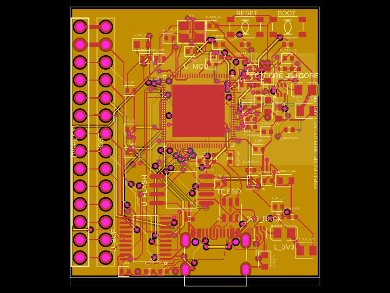 More from this authorseveibar/spi-display-webcam-interceptorThis collection of code defines various hardware components, including an crystal oscillator, microcontroller, voltage regulators, inductors, connectors, and logic gates, each represented with physical footprint, pin configurations, and 3D CAD models for PCB design and integration.
 Similar packageaura/diy-power-delivery-triggerThis hardware design implements a USB Type-C port with supporting power management and signal conditioning components, including a USB-C connector, a FUSB302 USB-C port controller, ESD protection diodes, a buck converter for 3.3V power regulation, an STM32 microcontroller for control and processing, an RGB LED indicator, push button, terminal block connections, and associated filtering and support components.
 Discover something newShiboSoftwareDev/mspm0g3507-usb-c-dev-boardThe circuit assembles a USB-C port with integrated ESD protection, power regulation, UART interface, and microcontroller (MSPM0G3507) with supporting components for USB data lines, CC termination, I2C, SPI, reset circuitry, and indicator LEDs.