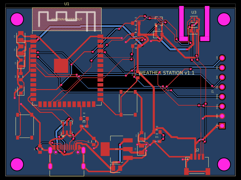
README.md
# RP2040 + TMC2209 motor-controller variant

Editable tscircuit design derived from [imrishabh18/rp2040-motor-controller](https://tscircuit.com/imrishabh18/rp2040-motor-controller), registry version **1.0.21**, retrieved 2026-09-23. The DRV8847 power stage is replaced with a **TMC2209-LA-T** (QFN-28 with exposed pad, JLCPCB C2150710).

**Design status: routed prototype; TypeScript, electrical connectivity, 29 firmware tests and the built-in PCB DRC pass. Not released for fabrication.** See `verification.md` for actual checks and review limits. No old saved routes, Gerbers or upstream validation claims are reused for this variant. It has not been tested on hardware.

## Preserved from the source

- 42.30 × 42.32 mm, four-layer, 1.6 mm NEMA 17 rear-mount outline; 31 mm mounting-hole spacing.
- RP2040, flash, programming USB-C, BOOT/RUN buttons and debug pads.
- Separate USB-C PD motor input and JST-PH motor connector; revised to request **12 V** with a 100 µF / 25 V bulk capacitor and SMBJ13CA TVS.
- TMP102 temperature monitoring, buzzer and optional bottom-mounted AS5600 encoder.
- AS5600 is still **DNP** as in the source. The supplied monitor intentionally refuses to arm without a working encoder/magnet. Fit it to use that monitor; do not silently bypass its check.

This revision requests **fixed 12 V**. It does not enable software selection of 15/20 V. A charger must offer 12 V; fallback is measured and the monitor refuses to arm outside 10.8–13.2 V.

## RGB status, ADC measurements and 12 V PD

- **D_RGB:** TUOZHAN TZ-0807Z1RGB-5V-I4-MS(5mA), **C26159667**, 2.0 × 1.8 mm, integrated HC-1815 controller, GRB serial data. Selected from the requested [JLCSearch LED-with-IC list](https://jlcsearch.tscircuit.com/led_with_ic/list), which listed 16,395 in stock on 2026-09-24. Stock is the available popularity proxy, not a usage count. The manufacturer specifies 5 mA per color. Firmware caps channels at 8/255 (about 0.16 mA average per color), using red for stopped/fault, amber for warm and green for enabled. It replaces the old GPIO25 indicator; the separate power indicator remains.
- **Logic levels:** SN74AHCT1G125DBVR, C7484, translates GPIO25's 3.3 V data to the programming USB's 5 V. LED and buffer have local 100 nF bypass capacitors, 100 Ω data damping and a buffer-input pull-down. Motor PD VBUS never powers the LED. `status_led.py` supplies the manufacturer's GRB timing and >80 µs reset interval. Verify pulse timing and color on first hardware.
- **PD voltage → GPIO28 / ADC2 (physical pin 40):** 100 kΩ / 10 kΩ, 1% divider plus 100 nF filter. `V_PD = ADC_voltage × 11`; 12 V produces about **1.091 V**. A BSS84 high-side switch with AO3400A gate control disconnects the divider when the 3.3 V rail is absent; two 100 kΩ gate resistors limit PMOS gate stress. The sense point is the motor USB connector, before the fuse. The switched divider avoids a sustained PD-only backfeed path into the unpowered RP2040.
- **Motor-supply current → GPIO29 / ADC3 (physical pin 41):** separate **50 mΩ, 1%, 1 W RLM12FTCMR050 (C912768)** after the fuse; **INA180A1IDBVR (C122228)** at 3.3 V, gain 20, followed by 1 kΩ / 100 nF. Nominal conversion is **1 V/A**. The shunt dissipates 0.2 W at 2 A. This measures positive current feeding the motor power stage, not phase currents or signed regenerative current. The two existing 0.15 Ω phase shunts remain connected only to the TMC2209 chopper-control inputs.
- **12 V selection:** CH224K CFG1 to ground through **24 kΩ, C23352**; CFG2 and CFG3 remain open per the manufacturer's resistor-mode table. The previous 6.8 kΩ requested 9 V. Bulk capacitor is now **TCJD107M025R0055E, C2159920, 100 µF / 25 V**; TVS is **SMBJ13CA, C224008**, with 13 V standoff and specified 21.5 V peak clamp. This is a 12 V configuration, not a 20 V design.

`power_telemetry.py` samples both ADCs, averages 16 readings, and supports calibration of the ADC reference and current offset. `main.py` prints `pd_V` and `motor_supply_A` with status. The guard checks power before arming and every 100 ms; out-of-range voltage or ≥1.8 A supply current stops the motor and requires explicit rearming. These firmware limits supplement the fuse/driver protections; they are not fast hardware overcurrent protection. Divider, reference and amplifier tolerances require calibration for accurate measurements. Regenerative current reads near zero with this unidirectional amplifier.

## Driver changes

| Function | This variant |
|---|---|
| Motor IC | TMC2209-LA-T, imported exact C2150710 footprint |
| STEP / DIR | GPIO18 / GPIO19 |
| UART0 | GPIO20 TX through 1 kΩ; GPIO21 RX directly on PDN_UART |
| UART address | 0; MS1_AD0 and MS2_AD1 grounded |
| Enable request | GPIO22, still active high at the MCU |
| Hardware interlock | SN74LVC1G00DBVR NAND, C7826, replaces the original AND gate |
| ENN | NAND output to driver pin 2; 10 kΩ pull-up to 3.3 V |
| DIAG | Driver pin 11 to GPIO23, **active high**; old nFAULT pull-up removed |
| Current sensing | Separate 0.15 Ω external shunts, RLH12FTCR150, 1206 / 1 W, C2683383 |
| Charge pump | 22 nF / 50 V CPI–CPO; 100 nF / 25 V VCP–VS |
| Local supplies | 2.2 µF / 10 V on 5VOUT; 100 nF / 10 V on VCC_IO; VS filtering at both supply pins |
| Ground | Pins 3, 18 and exposed pad 29; unused pin 25 also grounded |
| Other pins | CLK, STDBY and SPREAD grounded; VREF and INDEX intentionally open |
| Motor connector | Pin 1 OA1 (A+), 2 OA2 (A−), 3 OB1 (B+), 4 OB2 (B−) |

UART configuration must complete before enabling: digital current scaling (`I_scale_analog=0`), external sense resistors, `pdn_disable=1`, register-selected microsteps. VREF is intentionally unused in this mode.

The hardware enable equation is **ENN = NOT(PD_MCU_ENABLE AND TEMP_OK)**. A low GPIO22, loss of the PD permit, or active-low TMP102 ALERT forces ENN high and disables the bridges. The existing pull-downs retain the reset-disabled behavior. This change is necessary because DRV8847 nSLEEP and TMC2209 ENN have opposite polarities. The interlock is not a hardware fault latch; firmware requires explicit rearming.

## Firmware

`firmware/tmc2209.py` adds UART datagrams with CRC validation, local-echo filtering, response timeouts, IOIN identity checks and IFCNT-confirmed writes. `thermal_guard.py` initializes the driver while disabled, monitors UART status and interprets DIAG with the correct polarity. Stopping clears STEP/DIR and GPIO22 while leaving the UART pins assigned to UART0.

Initial settings are **16 microsteps**, 256-step interpolation, StealthChop, IRUN=14 and IHOLD=5. With 0.15 Ω shunts and VSENSE=0, nominal currents are approximately **0.63 A RMS running** and **0.25 A RMS holding**:

`I_RMS = ((CS + 1) / 32) × 0.325 / (0.15 + 0.020) / sqrt(2)`

These are starting settings, not a validated board current rating. Tune against the actual motor, supply and thermal measurements. The USB example remains a protection/monitoring program (`arm`, `stop`, `status`, `zero`); it does not generate motion. Implement STEP pulses only while `guard.policy.enabled`, and stop the pulse generator when that condition becomes false. Do not drive GPIO20/21 as the old coil outputs.

Copy the non-test Python modules in `firmware/` to RP2040 MicroPython. Apply both logic power and approved motor PD power before arming. UART failure, a TMC reset, driver temperature/short flags or an asserted DIAG during operation stops the guard. Firmware tests use mocked peripherals; they are not hardware validation.

## Build and inspect

```sh
bun install --frozen-lockfile
bun run typecheck
bun run render:schematic
python3 scripts/verify-connectivity.py dist/schematic/circuit.json
bun run test:firmware
bun run build
bun run dev
```

A newly generated candidate is saved in `routing/route-plan.json`. Its loader checks the complete routing input and refuses to apply it after geometry or connectivity changes. These are this variant's routes, not the upstream DRV8847 routes. To regenerate, run `bun scripts/capture-routing.tsx`, then `bun scripts/route.ts` and rebuild. Capture is an intermediate placement/connectivity export with intentionally empty routing; it is not the published PCB. Route corrections are tied to the exact input hash and must be re-reviewed after circuit edits.

The pinned router stalled in trace simplification. The regeneration script sets that optimizer's public loop limit to zero before it runs; it retains the unsimplified routes and still executes trace-width assignment, both DRC repair passes, power expansion, and normal core DRC. Any local route repairs for this revision are preserved in `routing/trace-overrides.json`. Candidate status and remaining errors are recorded in `verification.md`.

The exact toolchain is pinned in `bun.lock`. The original common-module patch is retained. A small additional fanout-solver type patch resolves a readonly-array incompatibility with the pinned capacity-router types; it changes no routing behavior.

`dist/schematic/` contains the rendered multi-sheet schematic and individual sheets. `dist/index/` contains the PCB build and its actual DRC records. `scripts/verify-connectivity.py` checks the rendered physical pins, motor-output isolation, UART separation, supply rails, external shunts, charge pump, NAND interlock and intentionally unused pins. It reports PCB errors without suppressing them.

## Layout and assembly work before fabrication

Review motor and sense-path widths, Kelvin returns, local capacitor loops and the exposed-pad ground/thermal-via design. The routed design includes through vias in SMT pads: use filled/capped via-in-pad fabrication, or redesign those escapes before assembly. No Gerber release is included. The broad 15 mm capacitor routing limit permits exploration of supply-network paths; it is **not** acceptance of a 15 mm high-frequency bypass loop. Minimize the driver-local loops manually. Verify thermal coupling from the moved TMP102 to the TMC2209.

The new current shunts require **0.15 Ω, 1%, 1206, 1 W RLH12FTCR150 (C2683383)**. Capacitor voltage ratings are encoded in the source. Review the parts engine's supplier substitutions against these ratings, DC-bias behavior and package land patterns before an assembly BOM is released. The source's supplier footprint-mismatch warnings remain relevant.

After layout review, check ENN stays high on boot and on missing PD/temperature faults, then verify UART register readback with the motor disconnected. Bring up at the initial low current, scope supply transients and STEP/DIR, measure winding current and temperatures, and verify manual rearming. Confirm motor screw clearance, encoder magnet spacing and optional encoder population.

## References and provenance

- [Original project](https://tscircuit.com/imrishabh18/rp2040-motor-controller); original README preserved as `UPSTREAM-README.md` for provenance, not as this variant's validation report.
- [Analog Devices TMC2209 Rev. 1.09 datasheet](https://www.analog.com/media/en/technical-documentation/data-sheets/tmc2209_datasheet_rev1.09.pdf): pinout, application circuit, UART, current scaling and layout.
- [TI SN74LVC1G00 datasheet](https://www.ti.com/lit/ds/symlink/sn74lvc1g00.pdf): NAND interlock.

- [TUOZHAN LED manufacturer datasheet](https://datasheet.lcsc.com/datasheet/pdf/1c77335c1ffc15867d272498d3d1ced7.pdf): 5 mA channels, physical pin map, supply, logic and GRB timing.
- [TI INA180 datasheet](https://www.ti.com/lit/ds/symlink/ina180.pdf): gain, common-mode range, physical pins and output filter.
- [TI SN74AHCT1G125 datasheet](https://www.ti.com/lit/ds/symlink/sn74ahct1g125.pdf): 5 V supply and TTL-compatible input.
- [WCH CH224 datasheet](https://www.wch-ic.com/downloads/CH224DS1_PDF.html): 24 kΩ / 12 V configuration.