seveibar/minimal-rp2040
This design features a Raspberry Pi RP2040 microcontroller with integrated decoupling capacitors, QSPI flash memory, crystal oscillator, and USB power circuitry, all mounted on a 65mm by 60mm four-layer PCB.
Usage: To import and use the RP2040 component in a tscircuit project: 1. Import the component: ```tsx import { RP2040 } from "@tsci/seveibar.minimal-rp2040" ``` 2. Use the component in a board: ```tsx <board> <RP2040 name="U3" pcbX={0} pcbY={0} connections={{ IOVDD1: "net.V3V3", // Add other required connections }} /> </board> ``` Key points: - Specify a name for the component - Set position using `pcbX` and `pcbY` - Define necessary network connections in the `connections` prop - Ensure proper power and ground connections
- Version
- 1.0.1
- License
- unset
- Stars
- 1
lib/thirdparty/RP2040DisplayBoard2.tsx
// RP2040DisplayBoard2.tsx
// Board with TFT 2.4" SPI Touchscreen (ILI9341) and 12x12mm tactile buttons
// Both display and buttons are bottom-mounted

import { Rp2040Zero } from "./RP2040Zero"
import { TFT_ILI9341_2_4in_SPI } from "../../imports/TFT_ILI9341_2_4in_SPI"
import { TactileButton12x12 } from "../../imports/TactileButton12x12"

export const RP2040DisplayBoard2 = () => (
  <board
    width="80mm"
    height="90mm"
    borderRadius="2mm"
    autorouter="laser_prefab"
    layers={2}
  >
    {/* RP2040-Zero module - top mounted at bottom of board */}
    <Rp2040Zero
      name="U1"
      pcbX="0mm"
      pcbY="-30mm"
      pcbRotation={180}
      connections={{
        GND: "net.GND",
        V3_3: "net.VCC",
        // Display SPI connections
        GP2: "net.LCD_SCK",
        GP3: "net.LCD_MOSI",
        GP4: "net.LCD_MISO",
        GP5: "net.LCD_CS",
        GP6: "net.LCD_DC",
        GP7: "net.LCD_RESET",
        GP8: "net.LCD_LED",
        // Touch SPI connections (shared clock/data lines)
        GP9: "net.TOUCH_CS",
        GP10: "net.LCD_SCK", // Share clock with display
        GP11: "net.LCD_MOSI", // Share MOSI with display
        GP12: "net.TOUCH_DO",
        GP13: "net.TOUCH_IRQ",
        // Button connections
        GP26: "net.BTN1",
        GP27: "net.BTN2",
        GP28: "net.BTN3",
        GP29: "net.BTN4",
      }}
    />

    {/* TFT 2.4" SPI Display - bottom mounted, at top of board */}
    <TFT_ILI9341_2_4in_SPI
      name="LCD1"
      pcbX="0mm"
      pcbY="18mm"
      pcbRotation={0}
      layer="bottom"
      connections={{
        VCC: "net.VCC",
        GND: "net.GND",
        CS: "net.LCD_CS",
        RESET: "net.LCD_RESET",
        DC: "net.LCD_DC",
        SDI: "net.LCD_MOSI",
        SCK: "net.LCD_SCK",
        LED: "net.VCC", // Backlight always on (can connect to GPIO for PWM control)
        SDO: "net.LCD_MISO",
        T_CLK: "net.LCD_SCK",
        T_CS: "net.TOUCH_CS",
        T_DIN: "net.LCD_MOSI",
        T_DO: "net.TOUCH_DO",
        T_IRQ: "net.TOUCH_IRQ",
      }}
    />

    {/* 12x12mm Tactile Buttons - bottom mounted, left and right of RP2040 */}
    {/* Button 1 - Left Upper */}
    <TactileButton12x12
      name="SW1"
      pcbX="-28mm"
      pcbY="-22mm"
      layer="bottom"
      connections={{
        pin1: "net.BTN1",
        pin2: "net.BTN1",
        pin3: "net.GND",
        pin4: "net.GND",
      }}
    />

    {/* Button 2 - Left Lower */}
    <TactileButton12x12
      name="SW2"
      pcbX="-28mm"
      pcbY="-38mm"
      layer="bottom"
      connections={{
        pin1: "net.BTN2",
        pin2: "net.BTN2",
        pin3: "net.GND",
        pin4: "net.GND",
      }}
    />

    {/* Button 3 - Right Upper */}
    <TactileButton12x12
      name="SW3"
      pcbX="28mm"
      pcbY="-22mm"
      layer="bottom"
      connections={{
        pin1: "net.BTN3",
        pin2: "net.BTN3",
        pin3: "net.GND",
        pin4: "net.GND",
      }}
    />

    {/* Button 4 - Right Lower */}
    <TactileButton12x12
      name="SW4"
      pcbX="28mm"
      pcbY="-38mm"
      layer="bottom"
      connections={{
        pin1: "net.BTN4",
        pin2: "net.BTN4",
        pin3: "net.GND",
        pin4: "net.GND",
      }}
    />
  </board>
)
Related Packages
 More from this authortscircuit/autorouting-dataset-01This code manages the hardware and electronic components for circuit design and PCB layout, defining components like resistors, capacitors, transistors, connectors, and footprints, and providing tools for component placement, PCB topology, and electrical connections.
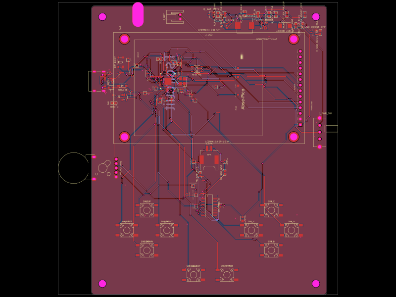 Similar packageabse/gameboyThis code defines the hardware mapping and schematic connections for a Raspberry Pi Pico-based development board featuring RP2040 microcontroller, USB-C connector, various power regulation components, decoupling capacitors, resistors, LEDs, headers, and supporting passive components for signal integrity and debugging.
 Discover something newimrishabh18/fitness_watchThis circuit integrates an ESP-12E microcontroller with various sensors, relays, and power management components, including an AO3400A transistor for switching loads, to enable wireless control and sensing functions.