rushabhcodes/fidget-counter
A tscircuit package created by rushabhcodes.
- Version
- 1.0.31
- License
- unset
- Stars
- 0
mechanical/MANUFACTURING_REVIEW.md
# Push-fit printed pilot review

Scope: confirmed 10–50-unit PETG pilot, rotation only. Reference: [Ploopy product](https://ploopy.co/knob/), [assembly](https://ploopyco.github.io/knob/assembly-instructions/) and [hardware](https://ploopyco.github.io/knob/appendices/hardware/), checked 2026-11-03. Its bearing-in-cap/push-on-base sequence and two PCB screws guide this independent design; its smaller bearing and electronics are not interchangeable.

| Per-unit inventory | Earlier press pilot | Previous RevC | Current push-fit pilot |
| --- | ---: | ---: | ---: |
| Rigid prints | 5 | 4 | 2 |
| Screw drives | 10 | 5 | 2 |
| Return springs | 3 | 0 | 0 |
| Handled parts, PCBA counted as one | 27 | 14 | 9 |
| Adhesive joints | 3 | 2 | 2 |
| Fitted electronics | 31 | 28 | 27 |

The nine parts are base, cap, bearing, two nylon PCB screws, PCBA, cell, encoder magnet and attachment ring. No top screws, separate nut/retainer or split assembly nest are used. Adhesive, shims, consumables and reusable tools are excluded. Use [assembly sequence](../MECHANICAL.md) and log preparation, cure, touch time and rework separately in ASSEMBLY_TIME_STUDY.csv. Savings are unmeasured.

The 6808-ZZ/61808-2Z bearing is40×52×7 atZ6.1–13.1. BaseØ58 and maximumcapØ61.6 remain; physical height is now16.4mm. The compact cap has1.3mm nominal deck,1.2mm local encoder roof and0.78mm conservative JST clearance; see [the compact review](COMPACT_CAP_REVIEW.md). ShaftØ40.05 and boreØ51.95 intentionally provide0.05mm diametral interference, not clearance. Inner shoulderØ42 matches [NSK recommendation](https://www.nsk.com/engineering/products/bearings/ball-bearings/deep-groove-ball-bearings/single-row-deep-groove-ball-bearings/6808zz-dgbb-sr.html) and [ZKL maximum](https://www.zkl.cz/en/p/61808-2Z). This does not qualify every supplier's shields/races. The through boreØ37.3 leaves1.375mm shaft wall and0.4mm nominal radial board insertion clearance.

Two-screw board retention remains reversible and accessible. Snap tabs add printed strain/creep and tolerance sensitivity and are not needed for the present reduction. The push-fit bearing has no positive axial lock: light seating, retention and service cannot be inferred from nominal CAD interference. Calibrate coupons, measure forces and test creep before approving the concept. Keep the previous screw-retained revision available if force/retention goals cannot coexist.

## Digital checks and physical release gates

See validation/pushfit-cad-audit.json, print-readiness.json, print-wall-sections.json, pcb-insertion-audit.json, cr2450-holder-audit.json and the [PCB review](../validation/FABRICATION_REVIEW.md). Exact BREP/mesh comparisons, clearances, full insertion sweep, all11 cap interfaces and24 rotor samples are checked. All12 product STL alternatives were actually sliced with PrusaSlicer2.8.1, generic0.4mm/PETG,0.15mm layers/.20first,4walls,100%infill and per-part support modes; there are no slicer warnings. No physical print or force test has been performed.

Before batch release:

1. Confirm printer/material, calibrate the ten coupons and print one circular prototype. Measure shaft/bore, cleanup, seating force, pull-off force, race/shield contact, free rotation, wobble, repeated service, PETG creep and phone/magnet/drop loads. Hand-only seating is required; never force through the bearing balls.
2. Qualify two nylon screws: post strength, torque, board deflection, shock and vibration. Four drills/posts remain if testing requires four screws. PCB edge webs are0.55mm and post pilot walls0.8mm.
3. Inspect the actual C7525448 loaded holder/cell. CAD includes limited free-state spring-contact interference; it does not establish loaded contact force, polarity, reflow or cell insertion/removal reliability. Nominal cell/floor clearance is0.5mm.
4. Qualify both adhesive joints and supplier-specific ring dimensions/polarity, peel/shear, cure and aging. Keep the encoder seated at its stop; no axial glue layer.
5. Verify the JLCPCB BOM/CPL assembly preview, particularly bottom BT1 positive pin1 and supplier rotation. Confirm exact stock, attrition, Standard PCBA/ENIG capability for the sensor, stencil, board stack and antenna fixture requirements before ordering.
6. Measure Hall/count accuracy with bearing/ring/phone, oscillator operation, RF matching/radiated performance, battery consumption/runtime. L2±5% is a conditional RF starting value. Pilot firmware, build checks and a BLE reader/reset client are in firmware/. Actual flashing, count accuracy, runtime and end-of-line qualification remain open.
7. Measure assembly time/yield/rework across multiple units before authorizing the 10–50-unit batch. Digital print/PCB checks are not a manufacturing qualification.

The initial unrestricted latest-tscircuit trial failed constraints. The active circuit now uses the refined0.0.3060 fresh routing, with new critical paths and local repairs, verified by the compiler, strict routing contracts, native KiCad DRC and actual Gerber artwork checks. Historical spring/thread/retainer revisions remain in Git history and do not qualify current retention.

The 1.0.30 electrical correction removes C7, changes C8 to 100 pF on DEC3 and isolates the C3 return through VSS31. Printed parts, height and handled assembly count remain unchanged. See [the review resolution](../validation/AI_REVIEW_RESOLUTION.md) for the corrected files and remaining RF/retention gates.
Related Packages
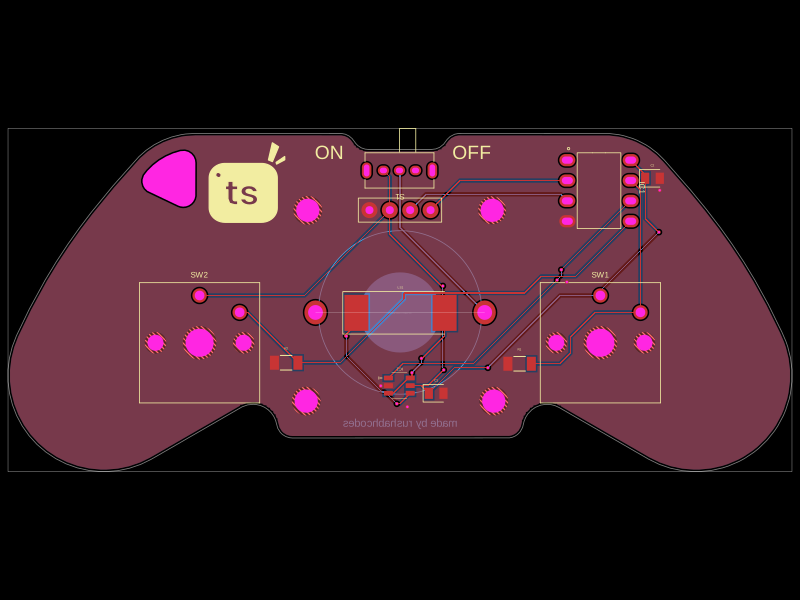 More from this authorrushabhcodes/Attiny85-Arcade-KeychainThis code defines a PCB and electronic component assembly for a compact ATtiny85-based gamepad keychain featuring power management, an OLED display, pushbutton inputs, audio piezo driver, and mechanical mounting, all mapped onto a custom PCB outline.
 Discover something newhrithik18k/switch-pcb