rushabhcodes/fidget-counter
A modular enclosure assembly with a stationary base, tray, cell, PCB retainers, backing ring, magnets, and interchangeable snap-on rotor/grip caps in multiple styles.
- Version
- 1.0.9
- License
- unset
- Stars
- 0
index.circuit.tsx
PCB

Schematic

import {Fragment} from "react"
import {assembly} from "@tscircuit/core"
import {EnclosureAssembly, type CapStyle} from "./enclosure"
// Select any of the 11 CAP_STYLE_OPTIONS exported by enclosure.tsx.
const CAP_STYLE: CapStyle = "circular"
import {NRF52810,TMAG3001,HF_XTAL,LF_XTAL,RF_ANT,CapButton,BatteryHolder} from "./parts"
import {routeBoard} from "./routing"
import {Cap,Res,Ind} from "./passives"
import type {PartsEngine,TraceProps} from "@tscircuit/props"
// Keep the authored BOM and datasheet pin models deterministic in every CLI check.
const fixedPartsEngine:PartsEngine={findPart:({sourceComponent})=>sourceComponent.type==="source_component"?sourceComponent.supplier_part_numbers ?? {}:{}}
const hideText={"& silkscreentext":{visibility:"hidden" as const}}
const outline=Array.from({length:128},(_,i)=>({x:18.25*Math.cos(i*2*Math.PI/128),y:18.25*Math.sin(i*2*Math.PI/128)}))
const holes=[45,135,225,315].map(a=>({x:16.2*Math.cos(a*Math.PI/180),y:16.2*Math.sin(a*Math.PI/180)}))
const unused=Array.from({length:32},(_,i)=>`P0_${i.toString().padStart(2,"0")}`).filter(p=>!["P0_00","P0_01","P0_21","P0_26","P0_27","P0_28","P0_29"].includes(p)).concat(["NC","DCC"])
const selector=(s:string)=>s.replace(/^\.([^ .]+)\.([^ .]+)$/, ".$1 > .$2")
// Coordinates are in the source component's local PCB frame.
const localRoutes: Record<string,TraceProps["pcbPath"]>={
 ".U1.ANT":[{x:3.5,y:-.2},{x:3.71,y:-.4}],
 ".C3.pin1":[{x:-.75,y:.15},{x:-1.5,y:.15}],
 ".U1.P0_29":[{x:.6,y:3.7},{x:.45,y:3.85},
  {x:.45,y:3.85,via:true,fromLayer:"top",toLayer:"bottom"},{x:.45,y:3.85},
  {x:-.1,y:6},{x:13.5,y:6},{x:14.8,y:-2.9},
  {x:14.8,y:-2.9,via:true,fromLayer:"bottom",toLayer:"top"},{x:14.8,y:-2.9}],
 ".U1.SWDCLK":[{x:3.7,y:-2.2},{x:3.7,y:-2.9},
  {x:3.7,y:-2.9,via:true,fromLayer:"top",toLayer:"bottom"},{x:3.7,y:-2.9},
  {x:3.9,y:-3.5},{x:3.9,y:-17.2},{x:9.5,y:-17.2}],
 ".U1.DEC4":[{x:-1.4,y:3.65},{x:-.7,y:3.65},{x:-.7,y:5.5}],
 ".U1.DEC2":[{x:3.8,y:.6},{x:4.4,y:.45}],
 ".U1.DEC3":[{x:4.3,y:1}],
 ".U1.XC1":[{x:4,y:1.4},{x:4.9,y:1.65},{x:8.0499,y:1.65}],
 ".U1.XC2":[{x:4.35,y:1.8},{x:4.35,y:3.7}],
 ".U1.XL1":[{x:-3.9,y:1.8},{x:-4.15,y:2.07495}],
 ".U1.XL2":[{x:-3.9,y:1.4},{x:-3.9,y:-.47495}],
 ".C1.pin1":[{x:-1.2,y:0}],
 ".C2.pin1":[{x:-.51,y:-.9}],
 ".C11.pin1":[{x:-.375,y:.8}],
 ".C12.pin1":[{x:-.075,y:-.8}],
}
const orientMcuPath=(path:NonNullable<TraceProps["pcbPath"]>)=>path.map(point=>typeof point==="string"?point:{...point,x:-Number(point.y),y:Number(point.x)})
const Link=({a,b,w=.11}:{a:string,b:string,w?:number})=>{
 const rf=b!=="net.GND" && /\.(L1|L2|C3|C13|C14)\.|\.U1\.ANT/.test(a+b)
 const clock=/\.X[12]\.X[12]$/.test(b)
 return <trace name={a.replace(/^\./,"").replace(".","_").replace("pin","")} from={selector(a)} to={selector(b)} width={w} pcbStraightLine={rf && !localRoutes[a]}
  maxLength={clock?10:undefined} maxViaCount={clock || rf || [".U1.DEC3",".U1.DEC4"].includes(a)?0:undefined}
  pcbPath={localRoutes[a] && a.startsWith(".U1.")?orientMcuPath(localRoutes[a]!):localRoutes[a]} pcbPathRelativeTo={localRoutes[a]?selector(a):undefined}/>
}
const G=({p}:{p:string})=><Link a={p} b="net.GND"/>
export default ()=> <assembly.device name="FIDGET_COUNTER">
 <board name="FIDGET_COUNTER_REVA" title="MagSafe BLE Fidget Counter — PCB Rev A"
 outline={outline} thickness={1} layers={2} solderMaskColor="green" doubleSidedAssembly
 partsEngine={fixedPartsEngine}
 defaultViaTenting="top_and_bottom_tented" isViaInPadAllowed={false} schLayout={{layoutMode:"relative"}}
 pcbStyle={{viaHoleDiameter:.3,viaPadDiameter:.55}}
 autorouter={{local:true,algorithmFn:routeBoard,allowViaInPad:false}} minTraceWidth={.11}
 minViaHoleDiameter={.3} minViaPadDiameter={.55} minBoardEdgeClearance={.3} minTraceToHoleEdgeClearance={.25} minViaEdgeToPadEdgeClearance={.13}>
 <net name="GND" isGroundNet/>
 <net name="VBAT" isPowerNet/>
 {[
  {n:"SCL",p:"P0_26",x:-5.55,y:9.45},
  {n:"SDA",p:"P0_27",x:-6.1,y:10.1},
  {n:"HALL_INT",p:"P0_28",x:-6.65,y:9.45},
 ].map(({n,p,x,y},i)=><Fragment key={n}>
  <chip name={`GPIO_${n}`} pcbX={x} pcbY={y} layer="top" doNotPlace noSchematicRepresentation
   pinLabels={{pin1:"SIGNAL"}} pinAttributes={{pin1:{isPassive:true,mustBeConnected:true}}} connections={{pin1:`net.${n}`}} pcbSx={hideText}
   footprint="platedhole_d0.3_pd0.55"><courtyardcircle radius={.375}/></chip>
  <trace name={`GPIO_${n}_ESCAPE`} from={`.U1 > .${p}`} to={`.GPIO_${n} > .pin1`} width={.11}
   pcbPathRelativeTo={`.U1 > .${p}`}
   pcbPath={[{x:-2.999994,y:[1.799844,1.400048,.999998][i]}]}/>
 </Fragment>)}

 {holes.map((p,i)=><Fragment key={i}><hole name={`H${i+1}`} pcbX={p.x} pcbY={p.y} diameter={3.6}/></Fragment>)}
 {holes.map((p,i)=><Fragment key={i}><keepout shape="circle" pcbX={p.x} pcbY={p.y}
  radius={2.2} layers={["top","bottom"]}/></Fragment>)}
 <keepout shape="rect" pcbX={0} pcbY={15.8} width={7} height={4.4}
  layers={["top","bottom"]} excludeRefs={[".ANT1"]}/>
 {/* Reserve the underside of these top pads to prevent via drills in the lands. */}
 <keepout shape="rect" pcbX={-1.69} pcbY={6} width={.54} height={.64} layers={["bottom"]} excludeRefs={[".BT1"]}/>
 <keepout shape="rect" pcbX={-2.11} pcbY={1.2} width={.54} height={.64} layers={["bottom"]} excludeRefs={[".BT1"]}/>
 <NRF52810 name="U1" pcbX={-7.5} pcbY={5} noConnect={unused} noSchematicRepresentation/>
 <via name="EP_GND" pcbX={-3.65} pcbY={5.12} holeDiameter={.3} outerDiameter={.55} connectsTo="net.GND"/>
 <trace name="QFN_LOCAL_GND" from=".U1 > .VSS2" to=".EP_GND > .top" width={.11}
  pcbPathRelativeTo=".U1 > .VSS2" pcbPath={[{x:-.199898,y:2.999994}]}/>
 <trace name="VSS2_LOCAL_GND" from=".U1 > .VSS2" to=".U1 > .EP" width={.11}
  pcbPathRelativeTo=".U1 > .VSS2" pcbPath={[{x:-.199898,y:2.999994},{x:-.0009398,y:.00127}]}/>
 <trace name="VSS1_LOCAL_GND" from=".U1 > .VSS1" to=".U1 > .EP" width={.11}
  pcbPathRelativeTo=".U1 > .VSS1" pcbPath={[{x:-2.1,y:-1}]}/>
 <via name="C9_GND" pcbX={-6.675} pcbY={-.4} holeDiameter={.3} outerDiameter={.55} connectsTo="net.GND"/>
 <trace name="C9_LOCAL_GND" from=".C9 > .pin2" to=".C9_GND > .top" width={.11} pcbStraightLine/>
 <via name="C18_GND" pcbX={-6.8} pcbY={10.2} holeDiameter={.3} outerDiameter={.55} connectsTo="net.GND"/>
 <trace name="C18_LOCAL_GND" from=".C18 > .pin2" to=".C18_GND > .top" width={.11} pcbStraightLine maxLength={1.5}/>
 <via name="C17_GND" pcbX={10.4} pcbY={2.1} holeDiameter={.3} outerDiameter={.55} connectsTo="net.GND"/>
 <trace name="C17_LOCAL_GND" from=".C17 > .pin2" to=".C17_GND > .top" width={.11}
  pcbPathRelativeTo=".C17 > .pin2" pcbPath={[{x:2.1,y:-.9}]}/>
 <via name="C5_GND" pcbX={-13.4} pcbY={8.8} holeDiameter={.3} outerDiameter={.55} connectsTo="net.GND"/>
 <trace name="C5_LOCAL_GND" from=".C5 > .pin2" to=".C5_GND > .top" width={.11}
  pcbPathRelativeTo=".C5 > .pin2" pcbPath={[{x:1,y:-.5}]}/>
 <via name="C8_GND" pcbX={-1.1} pcbY={6.05} holeDiameter={.3} outerDiameter={.55} connectsTo="net.GND"/>
 <trace name="C8_LOCAL_GND" from=".C8 > .pin2" to=".C8_GND > .top" width={.11} pcbStraightLine/>
 <via name="C10_GND" pcbX={-6.1} pcbY={12.9} holeDiameter={.3} outerDiameter={.55} connectsTo="net.GND"/>
 <trace name="C10_LOCAL_GND" from=".C10 > .pin2" to=".C10_GND > .top" width={.11} pcbStraightLine/>
 <via name="X1_GND1" pcbX={-1.4} pcbY={7.4} holeDiameter={.3} outerDiameter={.55} connectsTo="net.GND"/>
 <trace name="X1_LOCAL_GND1" from=".X1 > .pin4" to=".X1_GND1 > .top" width={.11} pcbStraightLine/>
 <trace name="C8_X1_GND_BRIDGE" from=".C8_GND > .bottom" to=".X1_GND1 > .bottom" width={.11} pcbStraightLine/>
 <trace name="C8_EP_GND_BRIDGE" from=".C8_GND > .bottom" to=".EP_GND > .bottom" width={.11}
  pcbPath={[{x:0,y:-.75}]}/>
 <via name="X1_GND2" pcbX={1.4} pcbY={9} holeDiameter={.3} outerDiameter={.55} connectsTo="net.GND"/>
 <trace name="X1_LOCAL_GND2" from=".X1 > .pin2" to=".X1_GND2 > .top" width={.11} pcbStraightLine/>
 <via name="C1_GND" pcbX={2.8} pcbY={8.1} holeDiameter={.3} outerDiameter={.55} connectsTo="net.GND"/>
 <trace name="C1_LOCAL_GND" from=".C1 > .pin2" to=".C1_GND > .top" width={.11} pcbStraightLine/>
 <trace name="R4_LOCAL_VBAT" from=".C9 > .pin1" to=".R4 > .pin1" width={.11} pcbPathRelativeTo=".C9 > .pin1"
  pcbPath={[{x:-1,y:-1.45},{x:-1,y:-1.45,via:true,fromLayer:"top",toLayer:"bottom"},{x:-1,y:-1.45},
   {x:3.4,y:-1.45},{x:3.4,y:-1.45,via:true,fromLayer:"bottom",toLayer:"top"},{x:3.4,y:-1.45},{x:3.81,y:-1.04}]}/>
 <schematicsheet name="power-debug" displayName="Power and programming" sheetIndex={0}>
  <schematicsection name="power" displayName="CR2032 / LDO mode — DCDCEN = 0"/>
  <schematicsection name="debug" displayName="SWD pogo pads — underside"/>
  <schematicbox name="U1 Power" chipRef=".U1" schX={0} schY={1} width={1.96} height={1} schSectionName="power"
   pinLabels={{pin1:"VDD1",pin2:"VDD2",pin3:"VDD3",pin6:"DEC1",pin7:"DEC2",pin8:"DEC3",pin9:"DEC4"}}
   schPinArrangement={{leftSide:["pin1","pin2","pin3"],rightSide:["pin6","pin7","pin8","pin9"]}}/>
  <schematicbox name="U1 Ground" chipRef=".U1" schX={0} schY={-2.2} width={1.1} height={.8} schSectionName="power"
   pinLabels={{pin1:"VSS1",pin2:"VSS2",pin3:"EP"}}
   schPinArrangement={{leftSide:["pin1","pin2","pin3"],rightSide:[]}}/>
  <BatteryHolder name="BT1" layer="bottom" pcbX={-1.2} pcbY={0} pcbSx={hideText} schX={-6} schY={2} schOrientation="vertical" schSectionName="power"/>
  <Cap name="C4" capacitance="100nF" pcbX={-10} pcbY={.7} schX={-3.5} schY={2.5} schSectionName="power"/>
  <Cap name="C9" capacitance="4.7uF" pcbX={-7.5} pcbY={.5} schX={-3.5} schY={0} schSectionName="power"/>
  <Cap name="C15" capacitance="22uF" pcbX={-6} pcbY={-3.5} pcbRotation={180} schX={-6} schY={0} schSectionName="power"/>
  <Cap name="C5" capacitance="100nF" pcbX={-12.4} pcbY={8.42} pcbRotation={180} schX={4} schY={4} schSectionName="power"/>
  <Cap name="C7" capacitance="100pF" pcbX={0} pcbY={5.5} schX={4} schY={1.8} schSectionName="power"/>
  <Cap name="C8" capacitance="100nF" pcbX={-2.2} pcbY={6} schX={4} schY={-.4} schSectionName="power"/>
  <Cap name="C10" capacitance="1uF" pcbX={-7.4} pcbY={12} pcbRotation={90} schX={4} schY={-2.6} schSectionName="power"/>
  <Cap name="C16" capacitance="100nF" pcbX={-4.8} pcbY={9.9} pcbRotation={90} schX={-1.5} schY={-.5} schSectionName="power"/>
  <Cap name="C18" capacitance="100nF" maxDecouplingTraceLength={3} pcbX={-8.2} pcbY={9.4} schX={-5.3} schY={-1.7} schSectionName="power"/>
  <schematicbox name="U1 SWD" chipRef=".U1" schX={11} schY={1} width={2.4} height={.8} schSectionName="debug"
   pinLabels={{pin1:"SWDIO",pin2:"SWDCLK",pin3:"nRESET"}} schPinArrangement={{leftSide:[],rightSide:["pin1","pin2","pin3"]}}/>
  {[["TP_VDD","VBAT"],["TP_GND","GND"],["TP_SWDIO","SWDIO"],["TP_SWDCLK","SWDCLK"],["TP_RESET","NRESET"]].map(([name,n],i)=><testpoint
   key={name} name={name} footprintVariant={name==="TP_GND"?"through_hole":"pad"} holeDiameter={name==="TP_GND"?.4:undefined} padDiameter={1.2} layer="bottom" pcbX={-4+i*2} pcbY={-14}
   doNotPlace pcbSx={hideText} schX={15} schY={i===4?-4:3-i*1.5} schSectionName="debug" connections={{pin1:`net.${n}`}}
   footprint={name==="TP_GND"?"platedhole_d0.4_pd1.2":"smtpad_circle_d1.2"}><courtyardcircle radius={.75}/></testpoint>)}
  <Res name="R4" pcbSx={hideText} resistance="100k" pcbX={-4.2} pcbY={.7} pcbRotation={180} schX={11} schY={-3.5} schOrientation="vertical"
   schSectionName="debug" connections={{pin1:"net.VBAT",pin2:"net.NRESET"}}/>
  {["VDD1","VDD3"].map(p=><Link key={p} a={`.U1.${p}`} b="net.VBAT"/>)}
  <trace name="VDD2_LOCAL" from=".U1 > .VDD2" to=".C18 > .pin1" width={.11}
   pcbPathRelativeTo=".U1 > .VDD2" pcbPath={[{x:-3.9,y:-2.2},{x:-3.9,y:-1.4}]}/>
  <Link a=".BT1.pin1" b="net.VBAT"/><G p=".BT1.pin2"/>
  {["C4","C9","C15","C16","C18"].map(c=><Link key={c} a={`.${c}.pin1`} b="net.VBAT"/>)}
  {["C4","C15","C16","C7","C8","C10"].map(c=><G key={c} p={`.${c}.pin2`}/>)}
  <Link a=".U1.DEC1" b=".C5.pin1"/><Link a=".U1.DEC2" b=".C7.pin1"/>
  <Link a=".U1.DEC3" b=".C8.pin1"/><Link a=".U1.DEC4" b=".C10.pin1"/>
  <Link a=".U1.SWDIO" b="net.SWDIO"/><Link a=".U1.SWDCLK" b=".TP_SWDCLK.pin1"/><Link a=".U1.nRESET" b="net.NRESET"/>
 </schematicsheet>
 <schematicsheet name="sensor-button" displayName="Rotation and cap press" sheetIndex={1}>
  <schematicsection name="sensor" displayName="TMAG3001A2 — XY angle / address 0x34"/>
  <schematicsection name="button" displayName="Cap press — hold 2 seconds to clear count"/>
  <schematicbox name="U1 Sensor GPIO" chipRef=".U1" schX={-6} schY={1} width={2.6} height={.8} schSectionName="sensor"
   pinLabels={{pin1:"P0_26",pin2:"P0_27",pin3:"P0_28"}} schPinArrangement={{leftSide:[],rightSide:["pin1","pin2","pin3"]}}/>
  <TMAG3001 name="U2" pcbX={0} pcbY={0} schX={1} schY={1} schSectionName="sensor" schWidth={1.58} schHeight={.8}
   schPinArrangement={{leftSide:["SCL","SDA","INT"],rightSide:["VCC","ADDR","GND"]}}/>
  <Cap name="C6" capacitance="100nF" pcbX={-1.6} pcbY={1.2} schX={5} schY={2} schSectionName="sensor"/>
  {["SCL","SDA","HALL_INT"].map((n,i)=><Res key={n} name={`R${i+1}`} resistance="10k"
   pcbX={2.3} pcbY={1.5-i*1.5} pcbSx={hideText} schX={-3+i*1.5} schY={4} schOrientation="vertical"
   schSectionName="sensor" connections={{pin1:"net.VBAT",pin2:`net.${n}`}}/>)}
  <Link a=".U2.SCL" b="net.SCL"/>
  <Link a=".U2.SDA" b="net.SDA"/>
  <trace name="HALL_INT_LOCAL" from=".U2 > .INT" to=".GPIO_HALL_INT > .pin1" width={.11}
   pcbPathRelativeTo=".U2 > .INT" pcbPath={[{x:-.65,y:0},{x:-1.4,y:0},
    {x:-1.4,y:0,via:true,fromLayer:"top",toLayer:"bottom"},{x:-1.4,y:0},
    {x:-1.4,y:1.8},{x:-2.9,y:3.3},{x:-2.9,y:4.3},{x:-4.3,y:4.3},
    {x:-5.7,y:6.1},{x:-6.65,y:9.45}]}/>
  <Link a=".U2.VCC" b="net.VBAT"/><G p=".U2.GND"/><G p=".U2.ADDR"/>
  <Link a=".C6.pin1" b="net.VBAT"/><G p=".C6.pin2"/>
  <schematicbox name="U1 Cap GPIO" chipRef=".U1" schX={-4} schY={-4} width={2.6} height={.4} schSectionName="button"
   pinLabels={{pin1:"P0_29"}} schPinArrangement={{leftSide:[],rightSide:["pin1"]}}/>
  <CapButton name="SW1" pcbX={0} pcbY={-5} pcbRotation={0} schX={1} schY={-4} schSectionName="button"/>
  <Res name="R5" pcbSx={hideText} resistance="100k" pcbX={8} pcbY={0} schX={-1} schY={-2}
   schOrientation="vertical" schSectionName="button" connections={{pin1:"net.VBAT",pin2:"net.CAP_PRESS"}}/>
  <Cap name="C17" capacitance="10nF" pcbX={9.5} pcbY={0} pcbRotation={90} schX={4} schY={-4} schSectionName="button"/>
  <Link a=".U1.P0_29" b=".R5.pin2"/><Link a=".SW1.A" b="net.CAP_PRESS"/><G p=".SW1.B"/>
  <trace name="CAP_FILTER_LOCAL" from=".R5 > .pin2" to=".C17 > .pin1" width={.11}
   pcbPathRelativeTo=".R5 > .pin2" pcbPath={[{x:1,y:-.25}]}/>
  <Link a=".C17.pin1" b="net.CAP_PRESS"/>
 </schematicsheet>
 <schematicsheet name="clocks" displayName="Clock sources" sheetIndex={2}>
  <schematicsection name="hf" displayName="32 MHz — initial 12 pF load caps"/>
  <schematicsection name="lf" displayName="32.768 kHz — sleep clock"/>
  <schematicbox name="U1 HF" chipRef=".U1" schX={-5} schY={3} width={2.4} height={.6} schSectionName="hf"
   pinLabels={{pin1:"XC1",pin2:"XC2"}} schPinArrangement={{leftSide:[],rightSide:["pin1","pin2"]}}/>
  <HF_XTAL name="X1" pcbX={0} pcbY={8} pcbRotation={90} schX={0} schY={3} schSectionName="hf"/>
  <Cap name="C1" capacitance="12pF" pcbX={2.3} pcbY={7.3} schX={-2} schY={5} schSectionName="hf"/>
  <Cap name="C2" capacitance="12pF" pcbX={0} pcbY={10.5} schX={-2} schY={.5} schSectionName="hf"/>
  <Link a=".U1.XC1" b=".X1.X1"/><Link a=".U1.XC2" b=".X1.X2"/>
  <Link a=".C1.pin1" b=".X1.X1"/><Link a=".C2.pin1" b=".X1.X2"/>
  {[".X1.pin2",".X1.pin4",".C1.pin2",".C2.pin2"].map(p=><G key={p} p={p}/>)}
  <schematicbox name="U1 LF" chipRef=".U1" schX={-5} schY={-4} width={2.4} height={.6} schSectionName="lf"
   pinLabels={{pin1:"XL1",pin2:"XL2"}} schPinArrangement={{leftSide:[],rightSide:["pin1","pin2"]}}/>
  <LF_XTAL name="X2" pcbX={-13} pcbY={5.8} pcbRotation={270} schX={0} schY={-3.95} schSectionName="lf"/>
  <Cap name="C11" capacitance="12pF" pcbX={-14.8} pcbY={6.7} pcbRotation={270} schX={0} schY={-2} schSectionName="lf"/>
  <Cap name="C12" capacitance="12pF" pcbX={-14.8} pcbY={4.6} pcbRotation={90} schX={0} schY={-6.5} schSectionName="lf"/>
  <Link a=".U1.XL1" b=".X2.X1"/><Link a=".U1.XL2" b=".X2.X2"/>
  <Link a=".C11.pin1" b=".X2.X1"/><Link a=".C12.pin1" b=".X2.X2"/>
  <G p=".C11.pin2"/><G p=".C12.pin2"/>
 </schematicsheet>
 <schematicsheet name="rf" displayName="BLE RF matching" sheetIndex={3}>
  <schematicsection name="rf-front-end" displayName="BLE RF — tune in final assembly"/>
  <schematicbox name="U1 RF" chipRef=".U1" schX={-5} schY={2} width={2.4} height={.4} schSectionName="rf-front-end"
   pinLabels={{pin1:"ANT"}} schPinArrangement={{leftSide:[],rightSide:["pin1"]}}/>
  <Ind name="L1" pcbSx={hideText} inductance="3.9nH" pcbX={-2.8} pcbY={4.4} schX={-1} schY={2} schSectionName="rf-front-end"/>
  <Ind name="L2" pcbSx={hideText} inductance="6.8nH" pcbX={-.6} pcbY={4.4} schX={2.5} schY={2} schSectionName="rf-front-end"/>
  <Cap name="C3" capacitance="0.8pF" pcbX={-3.1} pcbY={2.4} pcbRotation={270} schX={-2.5} schY={0} schSectionName="rf-front-end"/>
  <Cap name="C13" capacitance="0.5pF" doNotPlace pcbX={-1.85} pcbY={2.8} pcbRotation={270} schX={.7} schY={0} schSectionName="rf-front-end"/>
  <Cap name="C14" capacitance="0.5pF" doNotPlace pcbX={.5} pcbY={2.8} pcbRotation={270} schX={4.2} schY={0} schSectionName="rf-front-end"/>
  <schematictext text="C13 / C14: DNP tuning sites" schX={2.5} schY={-2} fontSize={.25}/>
  <RF_ANT name="ANT1" pcbX={0} pcbY={16.9} schX={6} schY={2} schSectionName="rf-front-end"/>
  <Link a=".U1.ANT" b=".L1.pin1" w={.18}/><Link a=".C3.pin1" b=".L1.pin1" w={.18}/>
  <Link a=".L1.pin2" b=".L2.pin1" w={.5}/><Link a=".C13.pin1" b=".L2.pin1" w={.18}/>
  <trace name="RF_FEED" from=".L2 > .pin2" to=".ANT1 > .feed" width={.5} pcbPathRelativeTo=".L2 > .pin2"
   pcbPath={[{x:1.6,y:0},{x:4.9,y:3.3},{x:4.9,y:8},{x:-.924,y:9.1},{x:-.924,y:12.5}]}/>
  <Link a=".C14.pin1" b=".L2.pin2" w={.18}/>
  {["C3","C13","C14"].map(c=><G key={c} p={`.${c}.pin2`}/>)}
 </schematicsheet>
 <via name="C11_GND" pcbX={-15.8} pcbY={6.25} holeDiameter={.3} outerDiameter={.55} connectsTo="net.GND"/>
 <trace name="C11_LOCAL_GND" from=".C11 > .pin2" to=".C11_GND > .top" width={.11} pcbStraightLine/>
 <via name="C12_GND" pcbX={-15.8} pcbY={5.02} holeDiameter={.3} outerDiameter={.55} connectsTo="net.GND"/>
 <trace name="C12_LOCAL_GND" from=".C12 > .pin2" to=".C12_GND > .top" width={.11} pcbStraightLine/>
 {/* Junction vias retain the existing power-tree routing; these are tented
     routing features, not contacts or separately fitted components. */}
 <via name="BT_POS_JUNCTION" pcbX={2} pcbY={-11} holeDiameter={.3} outerDiameter={.55} connectsTo="net.VBAT"/>
 <via name="BT_NEG_JUNCTION" pcbX={-2} pcbY={-11} holeDiameter={.3} outerDiameter={.55} connectsTo="net.GND"/>
 <copperpour name="TOP_GND" layer="top" connectsTo="net.GND" clearance={.15} boardEdgeMargin={.35} coveredWithSolderMask/>
 <copperpour name="BOTTOM_GND" layer="bottom" connectsTo="net.GND" clearance={.15} boardEdgeMargin={.35} coveredWithSolderMask/>
 <silkscreentext text="FIDGET / A3" pcbX={0} pcbY={-10.5} fontSize={1.7}/>
 <silkscreentext text="HALL" pcbX={0} pcbY={-3} fontSize={1.7}/>
 <silkscreentext text="CAP" pcbX={0} pcbY={-8.6} fontSize={1.7}/>
 <silkscreentext text="RF CLEAR" pcbX={4.8} pcbY={13.3} fontSize={1.7}/>
 <silkscreentext text="+" layer="bottom" pcbX={-13} pcbY={-3.8} fontSize={1.7}/>
 <silkscreentext text="-" layer="bottom" pcbX={9.5} pcbY={-3.8} fontSize={1.7}/>
 {["V","G","D","C","R"].map((label,i)=><Fragment key={label}><silkscreentext text={label}
  layer="bottom" pcbX={-4+i*2} pcbY={-15.8} fontSize={1.7}/></Fragment>)}
</board>
 <EnclosureAssembly capStyle={CAP_STYLE}/>
</assembly.device>
Related Packages
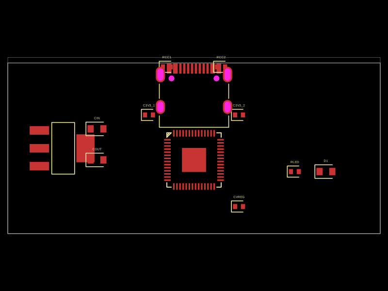 More from this authorrushabhcodes/RP2040A compact electronic circuit integrating a USB-C port, a voltage regulator (AMS1117 3.3V), a Raspberry Pi Pico RP2040 microcontroller, supporting power management, voltage regulation, and USB connectivity with associated passive components.
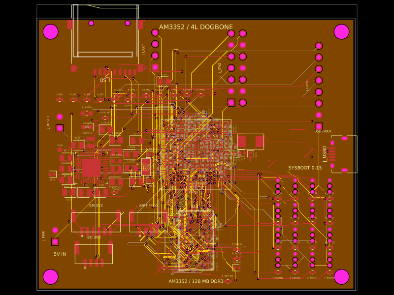 Similar packageseveibar/am3352-dev-board-4layer-dogboneDefines PCB footprints and pin mappings for a TI AM3352ZCZ100 processor, JST GH connectors, and assembly-part lookup helpers for capacitors, resistors, and headers.
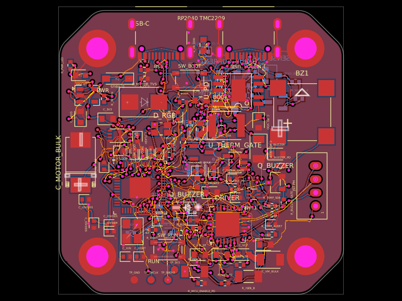 Discover something newseveibar/nema17-stepper-motor-driver-tmc2209-usb-pdRP2040-based USB-C PD stepper-motor controller with TMC2209 drive, AS5600 position feedback, TMP102 thermal shutdown, current/voltage telemetry, RGB status LED, and protected buzzer alarm circuitry.